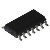
HFA3600IB Intersil, HFA3600IB Datasheet - Page 15

HFA3600IB
Manufacturer Part Number
HFA3600IB
Description
IC, LOW-NOISE AMP, 19.8DB 900MHZ SOIC-14
Manufacturer
Intersil
Datasheet
1.HFA3600IB.pdf
(16 pages)
Specifications of HFA3600IB
Frequency Range
900MHz
Noise Figure Typ
3.97dB
Power Dissipation Pd
1W
Supply Current
11.3mA
Supply Voltage Range
4V To 5.5V
Gain
19.8dB
Rf Type
Cellular, GSM, ISM, PCS
Lead Free Status / RoHS Status
Contains lead / RoHS non-compliant
NOTES:
HFA3600 Mixer Evaluation Notes
The evaluation of the HFA3600 mixer by itself is facilitated
by the demo-board design which provides access to the 3
ports by SMA connectors. As discussed before, RF to IF
feedthrough and LO to RF/IF ports moderate isolation can
cause errors during noise measurements.
The inherent RF to IF feedthrough of the single balanced
mixer mandates that noise measurements be single side
band only (with an appropriate band pass filter at the RF
frequency of interest). Because of this lack of isolation, the
incoming energy located at the IF passband from a
Saw, 3dB Loss
Short/No Filter
at the RF
Frequency
2. The single side band input filter (filter A) loss is accounted for and
3. The difference of a DSB to a SSB noise figure is theoretically
4. The cascaded results presented in the AC Specifications Table
IMAGE FILTER
BROADBAND
NOISE
SOURCE
TABLE 3. DSB MEASUREMENT SET UP
Filter, No Loss
HP346B
removed in the Noise figure and gain values.
3dB. The expected value of 2.2dB NF for a DSB measurement
is degraded to 3.6db due to a small attenuation of the
the image frequency.
of the data sheet are calculated assuming the use of an ideal
image filter (no loss) and a SSB measurement.
BROADBAND
NOISE
SOURCE
HP346B
FIGURE 37A. SSB NOISE FIGURE MEASUREMENT
FIGURE 37B. DSB NOISE FIGURE MEASUREMENT
(NO INPUT BANDPASS FILTER)
RF FREQ
FILTER A
TUNED
AT THE
LNA
(dB)
5.1
1.8
3.6
NF
GAIN
(dB)
16.0
19.0
LNA
31
HFA3600
15
FILTER
Equivalent to SSB
Measurement
Invalid Measurement
Note 3
HFA3600
FILTER
COMMENTS
LOW NOISE
LO
LOW NOISE
LO
HP8970A
FIGURE
METER
NOISE
HP8970A
FIGURE
METER
NOISE
filter at
HFA3600
broadband noise source for example, will feedthrough and
cause significant noise figure measurement errors.
As noise measurement equipment often makes use of
broadband noise sources with energy covering a wide
spectrum, SSB measurements are made using a band
pass filter in front of the RF port. The role of the band pass
filter is to prevent the image and IF noise energy from being
fed to the mixer.
However, band pass filters exhibit poor return losses at
frequencies outside their passbands. Because a moderate
amount of power from a local oscillator is transferred back to
the RF port in many active mixers, and this returned LO
signal is outside the passband of the SSB filter being used,
the signal will get reflected back again to the RF port due to
impedance mismatch between the filter and the RF port.
This impedance mismatch occurs at the LO frequency and
these multiple signal reflections can affect gain and noise
performance of the mixer. This situation, although not a
problem for the actual receiver design, can become a source
of error during mixer noise measurements.
To minimize the problem, the simplest method is to provide a
short connection (well below /4 of the LO frequency)
between the filter and the RF port. In case a coaxial cable
connection is required, it maybe necessary to provide a
length of cable which assures minimum degradation to the
noise figure reading. Long cables above 3 feet can provide
the required standing wave dissipation for measurements in
the 800MHz to 1GHz range. Note that long cable losses
must be taken into account for the purpose of noise figure
measurements. Adjustable line stretchers or isolators at the
RF input port could also be used to optimize noise figure
readings as an option for the mixer evaluation.
And finally, the recommendation of filtering the local
oscillator signal before applying it to the LO port is important
for accuracy of noise measurements when evaluating the
mixer by itself, due to the typical LO to IF feedthrough in
single balanced mixers.
HFA3600 LNA Evaluation Notes
The evaluation of the LNA is straightforward. SMA
connectors are provided in the demo-board. There are no
recommendations for evaluating the LNA block other than
using typical RF amplifier test techniques.
Final Note
The cascaded evaluation of the HFA3600 LNA and mixer
blocks including an image rejection or high pass filter is the
best method to obtain accurate results. The gain and noise
performance contribution of the LNA and filter to the
cascaded results surpass considerably the performance
contribution of the mixer. The data collected by cascading
the blocks together reflects the performance at the system
level which includes the filter of choice for a required design.


