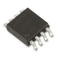
BD87A28FVM-TR Rohm Semiconductor, BD87A28FVM-TR Datasheet - Page 3

BD87A28FVM-TR
Manufacturer Part Number
BD87A28FVM-TR
Description
IC, VOLTAGE DETECTION, MSOP8
Manufacturer
Rohm Semiconductor
Series
-r
Type
Watchdog Circuitr
Specifications of BD87A28FVM-TR
Threshold Voltage
2.8V
No. Of Supervisors / Monitors
1
Supply Voltage Range
1V To 10V
Reset Type
Active-Low
Supply Current
5µA
Digital Ic Case Style
MSOP
No. Of Pins
8
Operating Temperature
RoHS Compliant
Number Of Voltages Monitored
1
Output
Open Drain or Open Collector
Reset
Active Low
Reset Timeout
Adjustable/Selectable
Voltage - Threshold
2.8V
Mounting Type
Surface Mount
Package / Case
8-VSSOP, 8-MSOP (0.110", 2.80mm Width)
Lead Free Status / Rohs Status
Lead free / RoHS Compliant
●Electrical characteristics (Unless otherwise specified, Ta = −40℃ to 105℃, VDD = 5 V)
© 2010 ROHM Co., Ltd. All rights reserved.
BD37A19FVM, BD37A41FVM, BD87A28FVM, BD87A29FVM,
BD87A34FVM, BD87A41FVM, BD99A41F
www.rohm.com
[Overall]
Total supply current 1
(during WDT operation)
Total supply current 2
(when WDT stopped)
Output leak current
Output current capacity
[RESET]
Detection
voltage 1
Detection
voltage 2
Hysteresis
width
RESET transmission
delay time: low high
Delay circuit resistance
Delay pin threshold voltage
Delay pin output current
Min. operating voltage
[WDT]
WDT monitor time
WDT reset time
Clock input pulse width
CLK high threshold voltage
CLK low threshold voltage
CLK high threshold voltage
CLK low threshold voltage
CTW charge current
CTW discharge current
*1
*2
*3
○
TPLH can be varied by changing the CT capacitance value.
TPLH (s) 0.69 × Rrst (MΩ) × CT (µF) Rrst = 10 MΩ
TwH can be varied by changing the CT capacitance value.
TwH (s) (0.5 × CTW (µF))/ICTWC (µA) ICTWC = 0.5 µA
TwL can be varied by changing the CTW capacitance value.
TwL (s) (0.5 × CTW (µF))/ICTWO (µA) ICTWO = 1.5 µA
Note: This IC is not designed to be radiation-resistant.
Parameter
1.9V Detect
2.8V Detect
2.9V Detect
3.4V Detect
4.1V Detect
1.9V Detect
2.8V Detect
2.9V Detect
3.4V Detect
4.1V Detect
1.9V Detect
2.8V Detect
2.9V Detect
3.4V Detect
4.1V Detect
TWCLK
Symbol
VCLKH
ICTWO
VDET1
VDET1
VDET1
VDET1
VDET1
VDET2
VDET2
VDET2
VDET2
VDET2
VCLKL
ICTWC
VINHH
VINHL
VCTH
VOPL
Vrhys
Vrhys
Vrhys
Vrhys
Vrhys
TPLH
IDD1
IDD2
Ileak
TwH
Rrst
TwL
IOL
ICT
VDET × 0.018 VDET × 0.045 VDET × 0.060
VDET × 0.018 VDET × 0.035 VDET × 0.050
VDET × 0.03 VDET × 0.13 VDET × 0.19
VDET × 0.02 VDET × 0.05 VDET × 0.06
VDET × 0.02 VDET × 0.05 VDET × 0.07
VDD × 0.3
VDD × 0.8
VDD × 0.8
1.871
2.758
2.886
3.349
4.039
1.852
2.730
2.857
3.315
4.007
Min.
0.25
0.75
150
500
0.7
3.9
5.8
1.0
7.0
2.4
—
—
—
0
0
VDD × 0.45
3/10
Limits
1.900
2.800
2.930
3.400
4.100
1.900
2.800
2.930
3.400
4.100
10.0
(Typ.)
(Typ.)
(Typ.)
Typ.
10.0
0.50
1.50
6.9
3.3
—
—
—
—
—
—
—
—
—
5
5
VDD × 0.6
VDD × 0.3
VDD × 0.3
1.929
2.842
2.974
3.451
4.162
1.948
2.870
3.003
3.485
4.202
Max.
VDD
VDD
10.1
14.5
20.0
0.75
2.00
7.0
14
14
—
—
—
—
1
Unit
MΩ
mA
µA
µA
µA
ms
µA
ms
ms
µA
µA
ns
V
V
V
V
V
V
V
V
V
V
V
V
V
V
V
V
V
V
V
V
V
INH : WDT ON Logic Input
CTW = 0.1 µF
INH : WDT OFF Logic Input
VDD = VDS = 10 V
VDD = 1.2 V, VDS = 0.5 V
Ta = 25℃
Ta = 25℃
Ta = 25℃
Ta = 25℃
Ta = 25℃
Ta = −40 to 105℃
Ta = −40 to 105℃
Ta = −40 to 105℃
Ta = −40 to 105℃
Ta = −40 to 105℃
Ta = −40 to 105℃
Ta = −40 to 105℃
Ta = −40 to 105℃
Ta = −40 to 105℃
Ta = −40 to 105℃
CT = 0.001 µF
When VDD = VDET 0.5 V
VCT = GND
RL = 470 KΩ
VDD = 1.50 V, VCT = 0.5 V
VOL ≤ 0.4 V, RL = 470 KΩ
CTW = 0.01 µF
CTW = 0.01 µF
VCTW = 0.2 V
VCTW = 0.8 V
Conditions
Technical Note
2010.12 - Rev.A
*1
*2
*3


