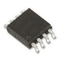
BD87A28FVM-TR Rohm Semiconductor, BD87A28FVM-TR Datasheet - Page 7

BD87A28FVM-TR
Manufacturer Part Number
BD87A28FVM-TR
Description
IC, VOLTAGE DETECTION, MSOP8
Manufacturer
Rohm Semiconductor
Series
-r
Type
Watchdog Circuitr
Specifications of BD87A28FVM-TR
Threshold Voltage
2.8V
No. Of Supervisors / Monitors
1
Supply Voltage Range
1V To 10V
Reset Type
Active-Low
Supply Current
5µA
Digital Ic Case Style
MSOP
No. Of Pins
8
Operating Temperature
RoHS Compliant
Number Of Voltages Monitored
1
Output
Open Drain or Open Collector
Reset
Active Low
Reset Timeout
Adjustable/Selectable
Voltage - Threshold
2.8V
Mounting Type
Surface Mount
Package / Case
8-VSSOP, 8-MSOP (0.110", 2.80mm Width)
Lead Free Status / Rohs Status
Lead free / RoHS Compliant
●Explanation
●Heat reduction curve
© 2010 ROHM Co., Ltd. All rights reserved.
BD37A19FVM, BD37A41FVM, BD87A28FVM, BD87A29FVM,
BD87A34FVM, BD87A41FVM, BD99A41F
www.rohm.com
1)
2)
3)
4)
5) The CTW pin state switches from charge to discharge when VCTW reaches VthL, and RESET switches from low to high.
6)
7)
8)
9)
10) RESET switches from high to low when VDD falls to the RESET detection voltage (VDET) or lower.
11) When VDD falls to 0 V, the RESET signal stays low until VDD reaches 0.8 V.
The RESET pin voltage (RESET) switches to low when the power supply voltage (VDD) falls to 0.8 V.
The external capacitor connected to the CT pin begins to charge when VDD rises above the reset detection voltage
(VDETH). The RESET signal stays low until VDD reaches the VDETH voltage and switches to high when VDD reaches
or exceeds the VDETH voltage. The RESET transmission delay time TPLH allowed to elapse before RESET switches
from low to high is given by the following equation:
Rrst denotes the IC's built-in resistance and is designed to be 10 MΩ (Typ.). CT denotes the external capacitor
connected to the CT pin.
The external capacitor connected to the CTW pin begins to charge when RESET rises, triggering the watchdog timer.
The CTW pin state switches from charge to discharge when the CTW pin voltage (VCTW) reaches VthH, and RESET
switches from high to low. The watchdog timer monitor time TWH is given by the following equation:
ICTWC denotes the CTW charge current and is designed to be 0.50 µA (Typ.). CTW denotes the external capacitor
connected to the CTW pin.
The watchdog timer reset time TWL is given by the following equation:
ICTWO denotes the CTW discharge current and is designed to be 1.50 µA (Typ.).
The CTW pin state may not switch from charge to discharge when the CLK input pulse width TWCLK is short. Use a
TWCLK input pulse width of at least 500 ns.
When a pulse (positive edge trigger) of at least 500 ns is input to the CLK pin while the CTW pin is charging, the CTW
state switches from charge to discharge. Once it discharges to VthL, it will charge again.
Watchdog timer operation is forced off when the INH pin switches to low:BD37A □□ FVM (Switches to high:
BD87A□□FVM, BD97A41F). At that time, only the watchdog timer is turned off. Reset detection is performed normally.
The watchdog timer function turns on when the INH pin switches to high. The external capacitor connected to the CTW
pin begins to charge at that time.
200
600
400
800
0
TPLH (s) 0.69 × Rrst × CT (µF) [1]
TWH (s) (0.5 × CTW (µF))/(ICTWC) [2]
TWL (s) (0.5 × CTW (µF))/(ICTWO) [3]
TWCLK ≥ 500 ns (Min.)
0
470mW
When mounted on a glass epoxy board
(70 mm 70 mm 1.6mm) ja = 212.8 (°C /W)
25
AMBIENT TEMPERATURE: Ta [℃]
50
MSOP8
75
100
105℃
125
Fig.17
7/10
200
600
400
800
0
0
550mW
When mounted on a glass epoxy board
(70 mm 70 mm 1.6mm) ja = 181.8 (°C /W)
25
AMBIENT TEMPERATURE: Ta [℃]
50
SOP8
75
100
105℃
Technical Note
2010.12 - Rev.A
125


