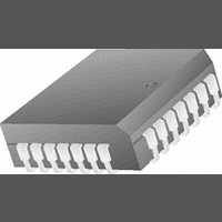
LM12H458CIV National Semiconductor, LM12H458CIV Datasheet - Page 31

LM12H458CIV
Manufacturer Part Number
LM12H458CIV
Description
A/D Converter (A-D) IC
Manufacturer
National Semiconductor
Datasheet
1.LM12H458CIV.pdf
(36 pages)
Specifications of LM12H458CIV
No. Of Pins
28
Peak Reflow Compatible (260 C)
No
Supply Voltage
5V
Supply Voltage Max
5V
No. Of Bits
12 Bit
Leaded Process Compatible
No
Mounting Type
Surface Mount
No. Of Channels
1
Number Of Elements
1
Sample Rate
182KSPS
Input Polarity
Bipolar
Input Type
Voltage
Rated Input Volt
±5V
Differential Input
Yes
Power Supply Requirement
Analog and Digital
Single Supply Voltage (typ)
5V
Single Supply Voltage (min)
3V
Single Supply Voltage (max)
5.5V
Dual Supply Voltage (typ)
Not RequiredV
Dual Supply Voltage (min)
Not RequiredV
Dual Supply Voltage (max)
Not RequiredV
Differential Linearity Error
±0.75LSB
Integral Nonlinearity Error
±1LSB
Operating Temp Range
-40C to 85C
Operating Temperature Classification
Industrial
Mounting
Surface Mount
Pin Count
44
Package Type
PLCC
Lead Free Status / RoHS Status
Contains lead / RoHS non-compliant
Lead Free Status / RoHS Status
Contains lead / RoHS non-compliant
Available stocks
Company
Part Number
Manufacturer
Quantity
Price
Company:
Part Number:
LM12H458CIV
Manufacturer:
Texas Instruments
Quantity:
10 000
Part Number:
LM12H458CIV
Manufacturer:
NS/国半
Quantity:
20 000
Company:
Part Number:
LM12H458CIV/NOPB
Manufacturer:
National Semiconductor
Quantity:
135
Company:
Part Number:
LM12H458CIV/NOPB
Manufacturer:
Intersil
Quantity:
188
Company:
Part Number:
LM12H458CIV/NOPB
Manufacturer:
Texas Instruments
Quantity:
10 000
Company:
Part Number:
LM12H458CIVF
Manufacturer:
Texas Instruments
Quantity:
10 000
5.0 Sequencer
Leaving this bit reset to “0” allows the Sequencer to execute
“unprogrammed” instructions, the results of which may be
unpredictable.
The Sequencer’s Instruction Pointer value is readable at any
time and is found in the Status register at Bits 8–10. The
Sequencer can go through eight states during instruction
execution:
the Instruction RAM “00”. This state is one clock cycle long.
This is the “rest” state whenever the Sequencer is stopped
using the reset, a Pause command, or the Start bit is reset
low (“0”). When the Start bit is set to a “1”, this state is one
clock cycle long.
figuration register is set to a “1”, state 2 is 76 clock cycles
long. If the Configuration register’s bit 3 is set to a “1”, state
2 is 4944 clock cycles long.
clock cycles for this state varies according to the value
stored in the Timer register. The number of clock cycles is
found by using the expression below
State 0: The current instruction’s first 16 bits are read from
State 1: Checks the state of the Calibration and Start bits.
State 2: Perform calibration. If bit 2 or bit 6 of the Con-
State 3: Run the internal 16-bit Timer. The number of
(Continued)
31
where 0 ≤ T ≤ 2
value if needed. The number of clock cycles for 12-bit + sign
mode varies according to
where D is the user-programmable 4-bit value stored in bits
12–15 of Instruction RAM “00” and is limited to 0 ≤ D ≤ 15.
The number of clock cycles for 8-bit + sign or “watchdog”
mode varies according to
where D is the user-programmable 4-bit value stored in bits
12–15 of Instruction RAM “00” and is limited to 0 ≤ D ≤ 15.
cycles long.
state takes 44 clock cycles when using the 12-bit + sign
mode or 21 clock cycles when using the 8-bit + sign mode.
The “watchdog” mode takes 5 clock cycles.
State 7: Run the acquisition delay and read Limit #1’s
State 6: Perform first comparison. This state is 5 clock
State 4: Read Limit #2. This state is 1 clock cycle long.
State 5: Perform a conversion or second comparison. This
16
−1.
32T + 2
9 + 2D
2 + 2D
www.national.com


