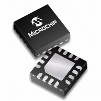
PIC16F676-E/ML Microchip Technology, PIC16F676-E/ML Datasheet - Page 39

PIC16F676-E/ML
Manufacturer Part Number
PIC16F676-E/ML
Description
1.75KB Flash, 64 RAM, 12 I/O 16 QFN 4x4mm TUBE
Manufacturer
Microchip Technology
Series
PIC® 16Fr
Datasheets
1.PIC16F616T-ISL.pdf
(8 pages)
2.PIC12F629T-ISN.pdf
(24 pages)
3.PIC16F630-ISL.pdf
(132 pages)
4.PIC16F630-ISL.pdf
(2 pages)
5.PIC16F630-ISL.pdf
(10 pages)
Specifications of PIC16F676-E/ML
Core Processor
PIC
Core Size
8-Bit
Speed
20MHz
Peripherals
Brown-out Detect/Reset, POR, WDT
Number Of I /o
12
Program Memory Size
1.75KB (1K x 14)
Program Memory Type
FLASH
Eeprom Size
128 x 8
Ram Size
64 x 8
Voltage - Supply (vcc/vdd)
2 V ~ 5.5 V
Data Converters
A/D 8x10b
Oscillator Type
Internal
Operating Temperature
-40°C ~ 125°C
Package / Case
16-QFN
Lead Free Status / RoHS Status
Lead free / RoHS Compliant
For Use With
AC164324 - MODULE SKT FOR MPLAB 8DFN/16QFN
Connectivity
-
Lead Free Status / RoHS Status
Lead free / RoHS Compliant, Lead free / RoHS Compliant
- PIC16F616T-ISL PDF datasheet
- PIC12F629T-ISN PDF datasheet #2
- PIC16F630-ISL PDF datasheet #3
- PIC16F630-ISL PDF datasheet #4
- PIC16F630-ISL PDF datasheet #5
- Current page: 39 of 132
- Download datasheet (2Mb)
6.0
The PIC16F630/676 devices have one analog compar-
ator. The inputs to the comparator are multiplexed with
the RA0 and RA1 pins. There is an on-chip Comparator
REGISTER 6-1:
2010 Microchip Technology Inc.
COMPARATOR MODULE
bit 7
bit 6
bit 5
bit 4
bit 3
bit 2-0
CMCON — COMPARATOR CONTROL REGISTER (ADDRESS: 19h)
bit 7
Unimplemented: Read as ‘0’
COUT: Comparator Output bit
When CINV = 0:
1 = V
0 = V
When CINV = 1:
1 = V
0 = V
Unimplemented: Read as ‘0’
CINV: Comparator Output Inversion bit
1 = Output inverted
0 = Output not inverted
CIS: Comparator Input Switch bit
When CM2:CM0 = 110 or 101:
1 = V
0 = V
CM2:CM0: Comparator Mode bits
Figure 6-2 shows the Comparator modes and CM2:CM0 bit settings
Legend:
R = Readable bit
- n = Value at POR
U-0
—
IN
IN
IN
IN
IN
IN
+ > V
+ < V
+ < V
+ > V
- connects to CIN+
- connects to CIN-
IN
IN
IN
IN
COUT
-
-
-
-
R-0
U-0
—
W = Writable bit
‘1’ = Bit is set
R/W-0
CINV
Voltage Reference that can also be applied to an input
of the comparator. In addition, RA2 can be configured
as the comparator output. The Comparator Control
Register (CMCON), shown in Register 6-1, contains
the bits to control the comparator.
R/W-0
U = Unimplemented bit, read as ‘0’
‘0’ = Bit is cleared
CIS
PIC16F630/676
R/W-0
CM2
x = Bit is unknown
R/W-0
CM1
DS40039F-page 39
R/W-0
CM0
bit 0
Related parts for PIC16F676-E/ML
Image
Part Number
Description
Manufacturer
Datasheet
Request
R

Part Number:
Description:
IC MCU FLASH 1K W/AD 14-SOIC
Manufacturer:
Microchip Technology
Datasheet:

Part Number:
Description:
IC MCU FLASH 1K W/AD 14-DIP
Manufacturer:
Microchip Technology
Datasheet:

Part Number:
Description:
IC MCU FLASH 1K W/AD 14-TSSOP
Manufacturer:
Microchip Technology
Datasheet:

Part Number:
Description:
IC MCU FLASH 1KX14 W/AD 14DIP
Manufacturer:
Microchip Technology
Datasheet:

Part Number:
Description:
14 PIN, 1.75KB STD FLASH, 64 RAM, 12 I/O,
Manufacturer:
Microchip Technology
Datasheet:

Part Number:
Description:
IC,MICROCONTROLLER,8-BIT,PIC CPU,CMOS,TSSOP,14PIN,PLASTIC
Manufacturer:
Microchip Technology
Datasheet:

Part Number:
Description:
1.75 KB Flash, 64 RAM, 12 I/O 16 QFN 4x4mm TUBE
Manufacturer:
Microchip Technology
Datasheet:

Part Number:
Description:
14-pin, Flash-based 8-bit Cmos Microcontroller
Manufacturer:
Microchip Technology Inc.
Datasheet:

Part Number:
Description:
IC, 8BIT MCU, PIC16F, 32MHZ, SOIC-18
Manufacturer:
Microchip Technology
Datasheet:

Part Number:
Description:
IC, 8BIT MCU, PIC16F, 32MHZ, SSOP-20
Manufacturer:
Microchip Technology
Datasheet:

Part Number:
Description:
IC, 8BIT MCU, PIC16F, 32MHZ, DIP-18
Manufacturer:
Microchip Technology
Datasheet:

Part Number:
Description:
IC, 8BIT MCU, PIC16F, 32MHZ, QFN-28
Manufacturer:
Microchip Technology
Datasheet:

Part Number:
Description:
IC, 8BIT MCU, PIC16F, 32MHZ, QFN-28
Manufacturer:
Microchip Technology
Datasheet:

Part Number:
Description:
IC, 8BIT MCU, PIC16F, 32MHZ, QFN-28
Manufacturer:
Microchip Technology
Datasheet:

Part Number:
Description:
IC, 8BIT MCU, PIC16F, 32MHZ, SSOP-20
Manufacturer:
Microchip Technology
Datasheet:


