EE2-24NU NEC, EE2-24NU Datasheet - Page 16
EE2-24NU
Manufacturer Part Number
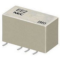
EE2-24NU
Description
SIGNAL RELAY, DPDT, 24VDC, 2A, SMD
Manufacturer
NEC
Datasheet
1.EE2-24NU.pdf
(18 pages)
Specifications of EE2-24NU
Contact Configuration
DPDT
Contact Current Max
2A
Contact Voltage Dc Nom
50V
Coil Voltage Vdc Nom
24V
Coil Resistance
2880ohm
Coil Power Cont
200mW
Relay Mounting
SMD
Coil Type
DC
Contact Voltage Ac Nom
250V
Rohs Compliant
Yes
Lead Free Status / RoHS Status
Lead free / RoHS Compliant
Available stocks
Company
Part Number
Manufacturer
Quantity
Price
Company:

Part Number:
EE2-24NU
Manufacturer:
HONGFA
Quantity:
5 400
Part Number:
EE2-24NU-L1
Manufacturer:
NEC
Quantity:
20 000
Company:
Part Number:
EE2-24NUH
Manufacturer:
KEMET
Quantity:
4 000
Company:
Part Number:
EE2-24NUH-L
Manufacturer:
KEMET
Quantity:
2 000
Company:
Part Number:
EE2-24NUN
Manufacturer:
NEC
Quantity:
5 400
Company:
Part Number:
EE2-24NUX
Manufacturer:
NEC
Quantity:
5 400


●All specifications in this catalog and production status of products are subject to change without notice. Prior to the purchase, please contact NEC TOKIN for updated product data.
●Please request for a specification sheet for detailed product data prior to the purchase.
●Before using the product in this catalog, please read "Precautions" and other safety precautions listed in the printed version catalog.
NOTE ON CORRECT USE
1. Notes on contact load
Make sure that the contact load is within the specified range;
otherwise, the lifetime of the contacts will be shortened
considerably.
Note that the running performance shown is an example,
and that it varies depending on parameters such as the
type of load, switching
ambient temperature under the actual operating conditions.
Evaluate the performance by using the actual circuit before
using the relay.
2. Driving relays
- If the internal connection diagram of a relay shows + and -
symbols on the coil, apply the rated voltage to the relay in
the specified
used, abnormalities such as beat at the coil may occur.
- The maximum voltage that can be applied to the coil of the
relay
Generally, the higher the voltage applied to the coil, the
shorter the operating time. Note, however, that a high
voltage also increases the bounce of the
the contact opening and closing frequency, which may
shorten the lifetime of the contacts.
- If the driving voltage waveform of the relay coil rises and
falls gradually, the inherent performance of the relay may not
be fully realized. Make sure that the voltage waveform
instantaneously rises and falls as a pulse.
- For a latching relay, apply a voltage to the coil according to
the polarity specified in the internal connection diagram of
the relay.
- If a current is applied to the coil over a long period of time,
the coil temperature rises, promoting generation of organic
gas inside the relay, which may result in faulty contacts. In
this case, use of a latching relay is recommended.
- The operating time and release time indicate the time
required for each contact to close after the voltage has been
applied to or removed from the coil. However, because the
relay has a mechanical structure, a bounce state exists at
the end of the operating and release times. Furthermore,
because additional time is required until the contact
stabilizes after being in a high-resistance state, care must be
taken when using the relay at high speeds.
3. Operating environment
- Make sure that the relay mounted in the application set is
used within the specified temperature range. Use of a relay
16
Nominal
coil voltage
0
varies depending on the ambient temperature.
<1msec.
direction. If a rippled DC current source is
frequency, driver circuit, and
<1msec.
contacts and
Humidity
(%RH)
at a temperature outside this range may adversely affect
insulation or contact performance.
- If the relay is used for a long period of time in highly humid
(RH 85% or higher) environment, moisture may be absorbed
into the relay. This moisture may react with the NOx and
SOx generated by glow discharges that occur when the
contacts are opened or closed, producing nitric or sulfuric
acid. If this happens, the acid produced may corrode the
metallic parts of the relay, causing operational malfunction.
-
and silicon based coating material) is used in the
neighborhood of relay, there is some possibility that these
materials will emit silicon gas that will penetrate the relay. In
this case, the switching contact may generate silicon
compounds on the surface of contacts. This silicon
compound may result in contact failure. Avoid use of relay in
such an environment.
-
depending on the humidity, use the relay in the temperature
range illustrated in the figure below. Prevent the relay from
being frozen and avoid the generation of condensation.
- The relay maintains constant sealability under normal
atmospheric pressure (810 to 1,200 hpa). Its sealability may
be degraded or the relay may be deformed and malfunction
if it is used under barometric conditions exceeding the
specified range.
- The same applies when the relay is stored or transported.
Keep the upper-limit value of the temperature to which the
relay is exposed after it is removed from the carton box to
within 50°C.
- Permanent magnets are used in polarized relays. For this
reason, when magnets, transformers, or speakers are
located nearby the relay characteristics may change and
faulty operations may result.
- If excessive vibration or shock is applied to the relay, it may
malfunction and the contacts remain closed. Vibration or
shock applied to the relay during operation may cause
considerable damage to or wearing of the contacts. Note that
operation of a snap switch mounted close to the relay or
shock due to the operation of magnetic solenoid may also
cause malfunctioning.
I
f any material containing silicon (silicon rubber, silicon oil,
Because
85
80
40
20
60
5
-60 -40 -20 0 20 40
the
operating
Temperature (
EC2/EE2 SERIES
temperature
°C
)
2007.08.03 P0888EMDD03VOL01E
60
range
80 100
varies
Related parts for EE2-24NU
Image
Part Number
Description
Manufacturer
Datasheet
Request
R


Part Number:
Description:
16/8 bit single-chip microcomputer
Manufacturer:
NEC
Datasheet:
Part Number:
Description:
Dual audio power amp circuit
Manufacturer:
NEC
Datasheet:
Part Number:
Description:
Dual comparator
Manufacturer:
NEC
Datasheet:
Part Number:
Description:
MOS type composite field effect transistor
Manufacturer:
NEC
Datasheet:
Part Number:
Description:
50 V/100 mA FET array incorporating 2 N-ch MOSFETs
Manufacturer:
NEC
Datasheet:
Part Number:
Description:
6-pin small MM high-frequency double transistor
Manufacturer:
NEC
Datasheet:
Part Number:
Description:
6-pin small MM high-frequency double transistor
Manufacturer:
NEC
Datasheet:
Part Number:
Description:
6-pin small MM high-frequency double transistor
Manufacturer:
NEC
Datasheet:
Part Number:
Description:
6-pin small MM high-frequency double transistor
Manufacturer:
NEC
Datasheet: