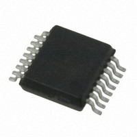
AS5130-ASST austriamicrosystems, AS5130-ASST Datasheet - Page 34

AS5130-ASST
Manufacturer Part Number
AS5130-ASST
Description
IC ENCODER ROTORY 8-BIT 16-SSOP
Manufacturer
austriamicrosystems
Type
Linear, Rotary Encoder - Programmabler
Datasheet
1.AS5130-ASST.pdf
(41 pages)
Specifications of AS5130-ASST
Sensing Range
32mT ~ 75mT
Voltage - Supply
4.5 V ~ 5.5 V
Current - Supply
24mA
Output Type
Analog, Ratiometric
Features
Programmable
Operating Temperature
-40°C ~ 125°C
Package / Case
16-SSOP
Lead Free Status / RoHS Status
Lead free / RoHS Compliant
Current - Output (max)
-
Other names
AS5130-ASSTTR
AS5130
Data Sheet - A p p l i c a t i o n I n f o r m a t i o n
8.4.4 Magnet Placement
Ideally, the center of the magnet, the diagonal center of the IC and the rotation axis of the magnet should be in one vertical line. The lateral
displacement of the magnet should be within ±0.25mm from the IC package center or +/-0.5mm from the IC center, including the placement of
the chip within the IC package. The vertical distance should be chosen such that the magnetic field on the die surface is within the specified
limits. The typical distance “z” between the magnet and the package surface is 0.5mm to 1.8mm with the recommended magnet (6mm x 2.5mm).
Larger gaps are possible, as long as the required magnetic field strength stays within the defined limits. A magnetic field outside the specified
range may still produce acceptable results, but with reduced accuracy. The out-of-range condition will be indicated, when the AGC is at the limits
(AGC= 0: field too strong; AGC=63=(3F
Figure 29. B
Figure 29
magnet, measured at a vertical distance of 1mm. The poles of the magnet (maximum level) are about 2.8mm from the magnet center, which is
almost at the outer magnet edges. The magnetic field reaches a peak amplitude of ~±106mT at the poles. The Hall elements are located at a
radius of 1mm (indicated as squares at the bottom of the graph). Due to the side view, the two Hall elements at the Y-axis are overlapping at
X=0mm, therefore only 3 Hall elements are shown. At 1mm radius, the peak amplitude is ~±46mT, respectively a differential amplitude of 92mT.
The vertical magnetic field B
the differential amplitude will be the same as for a centered magnet.
For example, if the magnet is misaligned in X-axis by -0.5mm, the two X-Hall sensors will measure 70mT (@ x = -1.5mm) and -22mt (@ x = -
0.5mm). Again, the differential amplitude is 92mT. At larger displacements however, the B
errors that mainly affect the accuracy of the system
www.austriamicrosystems.com/AS5130
3.5
shows a cross sectional view of the vertical magnetic field component Bz between the north and south pole of a 6mm diameter
z
Field Distribution Along the X-axis of a 6mmØ Diametric Magnetized Magnet
2.5
z
follows a fairly linear pattern up to about 1.5mm radius. Consequently, even if the magnet is not perfectly centered,
N
H
): field too weak or missing magnet).
1.5
(see Figure
Bz; 6mm magnet @y=0; z=1mm
X-displacement [mm]
0.5
31).
Revision 1.11
0
0.0015
0.001
0.0005
-0.001
-0.0005
-0.0015
-0.5
z
amplitude becomes nonlinear, which results in larger
-1.5
-2.5
S
-3.5
34 - 41


