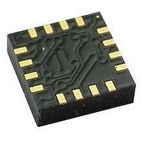
HMC5883L-TR Honeywell Microelectronics & Precision Sensors, HMC5883L-TR Datasheet - Page 17

HMC5883L-TR
Manufacturer Part Number
HMC5883L-TR
Description
IC COMPASS 3 AXIS I2C 16LCC SMD
Manufacturer
Honeywell Microelectronics & Precision Sensors
Series
HMCr
Type
Compass - Three Axisr
Specifications of HMC5883L-TR
Sensing Range
±8G
Voltage - Supply
2.16 V ~ 3.6 V
Current - Supply
100µA
Output Type
Differential Voltage
Features
Compass - Three Axis
Operating Temperature
-30°C ~ 85°C
Package / Case
16-LCC
Measuring Range
-8G To +8G
Resolution
5 MG
Supply Voltage Range
1.71V To 3.7V, 2.16V To 3.6V
No. Of Axes
3
Sensor Case Style
LCC
Ic Interface Type
I2C
Supply Voltage Max
3.6V
No. Of Pins
16
Resoluti
5 MG
Lead Free Status / RoHS Status
Lead free / RoHS Compliant
Current - Output (max)
-
Lead Free Status / RoHS Status
Lead free / RoHS Compliant
Other names
342-1082-2
Available stocks
Company
Part Number
Manufacturer
Quantity
Price
Company:
Part Number:
HMC5883L-TR
Manufacturer:
NSC
Quantity:
1 043
Part Number:
HMC5883L-TR
Manufacturer:
HONEYWELL
Quantity:
20 000
HMC5883L
unique 7-bit address. After each 8-bit transfer, the master device generates a 9
The receiving device (addressed slave) will pull the SDA line low to acknowledge (ACK) the successful transfer or leave
the SDA high to negative acknowledge (NACK).
Per the I
conditions on the bus associated with the SDA transitions when SCL is high. Master device pulling the SDA line low while
the SCL line is high indicates the Start (S) condition, and the Stop (P) condition is when the SDA line is pulled high while
the SCL line is high. The I
start condition without issuing a stop.
All bus transactions begin with the master device issuing the start sequence followed by the slave address byte. The
address byte contains the slave address; the upper 7 bits (bits7-1), and the Least Significant bit (LSb). The LSb of the
address byte designates if the operation is a read (LSb=1) or a write (LSb=0). At the 9
device will issue the ACK (or NACK). Following these bus events, the master will send data bytes for a write operation, or
the slave will clock out data with a read operation. All bus transactions are terminated with the master issuing a stop
sequence.
I
SDA and SCL lines as appropriate to allow the slave device to manipulate these lines. In a software implementation, care
must be taken to perform these tasks in code.
OPERATIONAL EXAMPLES
The HMC5883L has a fairly quick stabilization time from no voltage to stable and ready for data retrieval. The nominal 6
milli-seconds with the factory default single measurement mode means that the six bytes of magnetic data registers
(DXRA, DXRB, DZRA, DZRB, DYRA, and DYRB) are filled with a valid first measurement.
To change the measurement mode to continuous measurement mode, after the power-up time send the three bytes:
0x3C 0x02 0x00
This writes the 00 into the second register or mode register to switch from single to continuous measurement mode
setting. With the data rate at the factory default of 15Hz updates, a 67 milli-second typical delay should be allowed by the
I
0x3D, and clock out DXRA, DXRB, DZRA, DZRB, DYRA, and DYRB located in registers 3 through 8. The HMC5883L will
automatically re-point back to register 3 for the next 0x3D query. All six data registers must be read properly before new
data can be placed in any of these data registers.
SELF TEST OPERATION
To check the HMC5883L for proper operation, a self test feature in incorporated in which the sensor offset straps are
excited to create a nominal field strength (bias field) to be measured. To implement self test, the least significant bits (MS1
and MS0) of configuration register A are changed from 00 to 01 (positive bias) or 10 (negetive bias), e.g. 0x11 or 0x12.
Then, by placing the mode register into single-measurement mode (0x01), two data acquisition cycles will be made on
each magnetic vector. The first acquisition will be a set pulse followed shortly by measurement data of the external field.
The second acquisition will have the offset strap excited (about 10 mA) in the positive bias mode for X, Y, and Z axes to
create about a ±1.1 gauss self test field plus the external field. The first acquisition values will be subtracted from the
second acquisition, and the net measurement will be placed into the data output registers.
Since self test adds ~1.1 Gauss additional field to the existing field strength, using a reduced gain setting prevents sensor
from being saturated and data registers overflowed. For example, if the configuration register B is set to 0x60 (Gain=3),
values around +766 LSB (1.16 Ga * 660 LSB/Ga) will be placed in the X and Y data output registers and around +713
(1.08 Ga * 660 LSB/Ga) will be placed in Z data output register. To leave the self test mode, change MS1 and MS0 bit of
the configuration register A back to 00 (Normal Measurement Mode), e.g. 0x10.
www.honeywell.com
2
2
C bus control can be implemented with either hardware logic or in software. Typical hardware designs will release the
C master before querying the HMC5883L data registers for new measurements. To clock out the new data, send:
2
C spec, all transitions in the SDA line must occur when SCL is low. This requirement leads to two unique
2
C protocol also allows for the Restart condition in which the master device issues a second
th
clock pulse, and releases the SDA line.
th
clock pulse, the receiving slave
17


