P2CF-11 Omron, P2CF-11 Datasheet - Page 11
P2CF-11
Manufacturer Part Number
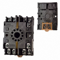
P2CF-11
Description
11 PIN Socket
Manufacturer
Omron
Type
Socketr
Specifications of P2CF-11
Number Of Positions
11
Mounting Type
DIN Rail
Termination Style
Screw Terminal
Accessory Type
Socket
Rohs Compliant
Yes
Associated Relay Series
H5CL
Number Of Poles
11
Mounting Style
DIN Rail
Lead Free Status / RoHS Status
Lead free / RoHS Compliant
For Use With/related Products
Multiple Series
For Use With
Z2998 - RELAY TIMER DGTL SPDT 100/240VACZ2366 - RELAY REPEAT CYCLE ANLG 30HRSZ997 - RELAY TIMER ANALOG 24VDC/ACZ2358 - RELAY REPEAT CYCLE ANLG 30HRSZ876 - RELAY TIMER DPDT ANALOG 120\240V
Lead Free Status / Rohs Status
Lead free / RoHS Compliant
Other names
P2CF11
Z884
Z884


Precautions
J POWER SUPPLIES
Apply the power supply voltage through a relay or switch so that
that the voltage reaches a fixed value immediately.
Turn the power ON and OFF with relay with a rated capacity of
10 A minimum to prevent contact deterioration due to inrush
current caused by turning the power ON and OFF.
J TIMER CONTROL WITH POWER START
The timer will function 160 to 250 ms after the power is turned
ON (refer to the above diagram). The control output will be
delayed for any set value less than 250 ms.
When the H5CL is used with power start in F mode (i.e.,
cumulative operation with output on hold), there will be a timer
error (approximately 100 ms each time the H5CL is turned on)
due to the characteristics of the internal circuitry. Use the H5CL
with signal start if timer accuracy is required.
J TRANSISTOR OUTPUT
The transistor output of the H5CL is insulated from the internal
circuitry by a photocoupler, so the transistor output can be used
as both NPN and PNP output.
The diode connected to the collector of the output transistor
is used to absorb inverted voltage that is generated when an
inductive load is connected to the H5CL.
J SELF-DIAGNOSTIC FUNCTION
The following displays will appear if an error occurs.
Note: This includes times when the life of the EEPROM has
When turning the power ON and OFF, input signal reception
is possible, unstable, or impossible (as shown here).
Power
supply
Display
e1
e2
Timer
Power for load
Load
expired.
ON
OFF
Input
Error
CPU
Memory
(See Note.)
Impossible
160 ms 0 to 90ms
Timer
Unstable
Output
status
OFF
Power for load
DC: 5 ms
AC: 10 ms
Possible
Inductive load
Correction
Press
RST Key
or turn
power off
and then
ON
Unstable
0 to 500 ms
Impossible
Set value
after
correction
No
change
0
11
J OPERATING ENVIRONMENT
When using the Timer in an area with excess electrical noise,
separate the Timer, wiring, and the equipment which generates
the input signals as far as possible from the noise sources. We
recommend shielding the input signal wiring to prevent electrical
interference. Organic solvents (such as paint thinner), as well as
very acidic or basic solutions can damage the outer casing of the
Timer.
J CHANGING THE PRESET VALUE
When changing the preset value during a timing operation, output
will turn ON if the preset value is changed as follows (since the
constant read-in system is in use):
Note: When in down mode, the changed amount of preset value
Reset with a Preset Value of 0
The output will go ON when the start signal is input. The output
will be OFF while the reset key is pressed or the reset input
is ON.
J MEMORY BACKUP
All data is stored in the EEPROM when there is power failure.
The EEPROM can be overwritten more than 200,000 times.
J PANEL MOUNTING
The H5CL’s panel surface is water-resistant, conforming to
NEMA 4 (indoors) and IP66. In order to prevent the internal
circuit from water penetration through the space between the
timer and operating panel, attach a rubber packing (provided with
the H5CL) between the timer and operating panel and secure the
rubber gasket with the Y92F-30 panel-mounting adapter.
J AVOID DAMAGE WHEN TESTING
When performing a dielectric strength test (or similar test) on the
H5CL mounted to a control panel, disconnect the H5CL from the
connecting circuit, or short-circuit all the terminals of the H5CL to
avoid damaging the H5CL.
J INTERNAL CONNECTIONS FOR DC
Terminal 1 (power supply terminal) and terminal 6 (input
common: 0 V for input) of DC model H5CL are internally
connected to each other.
J DIP SWITCH SELECTION
DIP switch setting while the H5CL is turned on will not be valid
until the H5CL is turned off and on.
Operating
mode
A mode
F mode
Display mode UP: Present value ≥ preset value
Display mode DOWN: Elapse time ≥ preset value
(Present value = 0)
MODEL
is added to or subtracted from the present value.
0.5 to 1 mm
Overwriting timing
When the H5CL is turned off after changing
the set value.
When the H5CL is turned off after changing
the set value, turning the start input, or the
reset input ON.
The space between the screw head and the
adapter should be 0.5 to 1 mm.
Related parts for P2CF-11
Image
Part Number
Description
Manufacturer
Datasheet
Request
R

Part Number:
Description:
SOCKET 8-PIN FOR H3CR-H
Manufacturer:
Omron
Datasheet:

Part Number:
Description:
SOCKET 11-PIN FOR H3CR-H
Manufacturer:
Omron
Datasheet:

Part Number:
Description:
8 PIN Socket
Manufacturer:
Omron
Datasheet:


Part Number:
Description:
G6S-2GLow Signal Relay
Manufacturer:
Omron Corporation
Datasheet:
Part Number:
Description:
Compact, Low-cost, SSR Switching 5 to 20 A
Manufacturer:
Omron Corporation
Datasheet:
Part Number:
Description:
Manufacturer:
Omron Corporation
Datasheet:
Part Number:
Description:
Manufacturer:
Omron Corporation
Datasheet:
Part Number:
Description:
Manufacturer:
Omron Corporation
Datasheet:
Part Number:
Description:
Manufacturer:
Omron Corporation
Datasheet: