P2CF-08-E Omron, P2CF-08-E Datasheet
P2CF-08-E
Specifications of P2CF-08-E
P2CF08E
Z2836
Available stocks


Related parts for P2CF-08-E


P2CF-08-E Summary of contents
Page 1
... Digital Timer H5CX H5CX Please read and understand this catalog before purchasing the products. Please consult your OMRON representative if you have any questions or comments. Refer to Safety Precautions (Common) on page 47. DIN 48 × 48-mm Multifunction Digital Timer/2-stage Digital Timer • Highly visible display with backlit negative transmissive LCD. ...
Page 2
Multifunction Digital Timer H5CX-A/-L DIN 48 × 48-mm Multifunction Digital Timer with a Bright, Easy-to-view, Negative Transmissive LCD. • Programmable PV color to visually alert when output status changes (screw terminal block models). • Intuitive setting enabled using DIP switch ...
Page 3
... Standard type Screw terminals 11-pin socket H5CX-A H5CX-A11 H5CX-AD H5CX-A11D H5CX-AS H5CX-A11S H5CX-ASD H5CX-A11SD Models Y92F-30 Y92S-29 P2CF-08 P2CF-08-E P2CF-11 P2CF-11-E P3G-08 P3G-08 with Y92A-48G (See note 2.) P3GA-11 P3GA-11 with Y92A-48G (See note 2.) Y92A-48 Y92A-48F1 PFP-50N PFP-100N PFP-100N2 PFP-M PFP-S H5CX-A/-L ...
Page 4
Specifications ■ Ratings Item Classification Digital timer Rated supply voltage 100 to 240 VAC (50/60 Hz), 24 VAC (50/60 Hz)/ VDC (permissible ripple: 20% (p-p) max.) Operating voltage range 85% to 110% rated supply voltage ( ...
Page 5
... Note 1. The values are based on the set value. 2. The value is applied for a minimum pulse width meet UL listing requirements with H5CX-L8@/-A11@ models, an OMRON P2CF-08-@ or P3G-08 Socket must be mounted on the Timer. Otherwise, H5CX-L8@/-A11@ models are considered to meet UL508 recognition requirements. ...
Page 6
Life-test Curve (Reference Values) 1,000 500 100 30 VDC L/R 250 VDC/30 VDC cosφ=1 10 250 VAC cosφ=0 Load current (A) Reference: A maximum current of 0.15 A can be switched at 125 ...
Page 7
Connections ■ Block Diagram (Basic insulation) Output circuit (Basic insulation) Internal control Input circuit circuit Note: Power circuit is not insulated from the input circuit, except for H5CX-A11/-A11S, which have basic insulation. ■ I/O Functions Inputs Start signal Reset Gate ...
Page 8
Terminal Arrangement Confirm that the power supply meets specifications before use. H5CX-A/-AD Input use 0 V Unused Unused Unused Unused Contact output (−) (+) The power ...
Page 9
Input Circuits Signal, Reset, and Gate Input + kΩ IN Internal circuit Note: When using no-voltage input (NPN input). ■ Input Connections The inputs of the H5CX-A@/-A11@ are no-voltage (short-circuit or open) inputs or voltage inputs. The ...
Page 10
Voltage Inputs (PNP Inputs) No-contact Input (NPN Transistor) (Connection to NPN open collector output sensor) Sensor 0 V H5CX-A@ H5CX-A@ H5CX-A11@ H5CX-A11@ Operate with transistor ON Operate with transistor OFF Voltage Input Signal Levels High level (Input ON): 4.5 to ...
Page 11
Nomenclature Indicator Reset Indicator (orange) Key Protection Indicator (orange) Control Output Indicator (orange) Present Value (red or green (programmable) for H5CX-A models, red for H5CX-A11 /-L models) Character height: 11.5 mm Time Unit Display (Color is same as present value ...
Page 12
Dimensions Note: All units are in millimeters unless otherwise indicated. ■ Dimensions without Flush Mounting Adapter H5CX-A/-AS (Flush Mounting Models) 48x48 H5CX-AD/-ASD (Flush Mounting Models) 48x48 H5CX-A11/-A11S (Flush Mounting/Surface Mounting Models) 48x48 H5CX-A11D/-A11SD (Flush Mounting/Surface Mounting Models) 48x48 H5CX-L8@ (Flush ...
Page 13
Dimensions with Flush Mounting Adapter H5CX-A/-AS (Provided with Adapter and Waterproof Packing) Y92S-29 (provided) Panel Waterproof Packing 58 48 H5CX-AD/-ASD (Provided with Adapter and Waterproof Packing) Y92S-29 (provided) Waterproof Packing 58 48 H5CX-A11/-A11S (Adapter and Waterproof Packing Ordered Separately) ...
Page 14
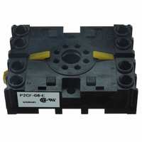
... Note: These dimensions vary with the kind of DIN track (reference value). ■ Accessories (Order Separately) Note: All units are in millimeters unless otherwise indicated. Track Mounting/Front Connecting Socket Eight, P2CF-08 M3.5 x 7.5 sems 70 max max. P2CF-08-E (Finger Safe Terminal Type) Conforming to VDE0106/P100 Eight, M3.5 x 7.5 sems 70 max. 4 40±0.2 50 max. H5CX- L8@ 100 ...
Page 15
... Track Mounting/Front Connecting Socket P2CF-11 Eleven, M3.5 x 7.5 sems 70 max max. P2CF-11-E (Finger Safe Terminal Type) Conforming to VDE0106/P100 Eleven, M3.5 x 7.5 sems 70 max. 4 40±0.2 50 max. Back Connecting Socket 27 dia. P3G- P3GA-11 27 dia Finger Safe Terminal Cover Conforming to VDE0106/P100 Y92A-48G (Attachment for P3G-08/P3GA-11 ...
Page 16
Soft Cover Hard Cover Y92A-48F1 Y92A-48 Flush Mounting Adapter (provided with models with H5CX-A/AD/AS/ASD) Y92F-30 Note: Order the Flush Mounting Adapter separately lost or dam- aged. Mounting Track PFP-100N, PFP-50N 7.3±0.15 4 ...
Page 17
Operating Procedures ■ Setting Procedure Guide Settings for Timer Operation Use the following settings for all models except the H5CX-L8@. Refer to page 19 for the H5CX-L8@. When Using Basic Functions Only Basic Functions • Time range (0.001 s to ...
Page 18
Operating Procedures (Timer Function) Settings for Basic Functions Settings for basic functions can be performed with just the DIP switch. ON OFF Item OFF 1 DIP switch set- Disabled Enabled tings enable/ disable 2 Time range Refer to the ...
Page 19
Settings for Advanced Functions Settings that cannot be performed with the DIP switch are performed with the operation keys. Power ON For details on operations in run mode, refer to page 21. Note 1. If the mode is switched to ...
Page 20
Explanation of Functions Time Range (timr) (Setting possible using DIP switch.) Set the range to be timed in the range 0.000 s to 9,999 h. Settings of type ---- h (9,999 h) and ---- min (9,999 min) cannot, however, be ...
Page 21
Operation in Run Mode When Output Mode Is Not Z Present value Set value When Output Mode Z Is Selected Present value ON duty ratio Present value Cycle time Present Value and Set Value These items are displayed when the ...
Page 22
Timing Charts Timer Operation The gate input is not included in the H5CX-L8@ models. One-shot output t Sustained output Either one-shot output or sustained output can be selected. Output mode A: Signal ON delay 1 (Timer resets when power comes ...
Page 23
Output mode b: Repeat cycle 1 (Timer resets when power comes ON.) Sustained Power Output Start signal Gate Reset Control output Set value UP Timing 0 diagram Set value DOWN 0 One-shot Power Output Start signal Gate Reset t ...
Page 24
Output mode d: Signal OFF delay (Timer resets when power comes ON.) Power Start signal Gate Reset Control output Set value UP Timing 0 diagram Set value DOWN 0 Output mode E: Interval (Timer resets when power comes ON.) Power ...
Page 25
Self-diagnostic Function The following displays will appear if an error occurs. Main display Sub-display e1 Not lit CPU Not lit Memory error (RAM) e2 Memory error (EEP) e2 sum (See note) Note: This includes times when the life of the ...
Page 26
Operating Procedures (Twin Timer Function) Switching from Timer to Twin Timer The H5CX is factory-set for timer operation. To switch to twin timer operation, use the procedure given below. For details, refer to page 32. Timer/twin timer selection mode ...
Page 27
Settings for Advanced Functions Settings that cannot be performed with the DIP switch are performed with the operation keys. Power ON For details on operations in run mode, refer to page 29. Note 1. If the mode is switched to ...
Page 28
Explanation of Functions OFF Time Range (oftr) (Setting possible using DIP switch.) Set the time range for the OFF time in the range 0.000 s to 9,999 h. Only settings of type --.-- s (99.99 s), ---.- s (999.9 s), ...
Page 29
Operation in Run Mode Present value OFF set time Present value ON set time Present Value and OFF Set Time The present value is displayed in the main display and the OFF set time is displayed in the sub-display. “SET1” ...
Page 30
Timing Charts Twin Timer Operation The gate input is not included in the H5CX-L8@ models. Sustained Power Output Start signal Gate Reset Control output OFF time UP ON time Timing 0 diagram OFF time DOWN ON time 0 Sustained Power ...
Page 31
Operation in Timer/Twin Timer Selection Mode Select whether the H5CX is used as a timer or a twin timer in timer/twin timer selection mode. The H5CX is also equipped with a DIP switch monitor function, a convenient function that ...
Page 32
Additional Information ■ Using the Operation Keys Timer Operation 1 s min. Timer/twin timer selection mode 1 s min. Timer/twin timer selection DIP switch monitor Twin Timer Operation + 1 s min. Timer/twin timer selection mode + 1 s min. ...
Page 33
List of Settings Fill in your set values in the set value column of the following tables and utilize the tables for quick reference. Timer/Twin Timer Selection Mode Parameter Parameter name Timer/Twin Tim- func tim/twin er selection DIP switch ...
Page 34
Settings for Twin Timer Operation Run Mode Parameter name Parameter Present value, OFF set time --- OFF set time --- --- --- --- --- --- --- --- --- Present value --- Present value, ON set time --- ON set time ...
Page 35
Digital Timer H5CX-B DIN 48 × 48-mm Digital Timer with 6-digit Display and Forecast Output • Times the daily operating hours of machinery and tools, predict- ing and notifying when maintenance is required. • The 2-stage settings and forecast ...
Page 36
Model Number Structure ■ Model Number Legend H5CX-BWSD Type classifier B: 6-digit display type 2. Stage setting W: 2-stage setting Ordering Information ■ List of Models Output type Supply voltage Transistor VDC ...
Page 37
Specifications ■ Ratings Item Classification Digital timer Rated supply voltage VDC (permissible ripple: 20% (p-p) max.) Operating voltage range 90% to 110% rated supply voltage Power consumption Approx. 2 VDC (See note 1.) Mounting ...
Page 38
Characteristics Item Power-ON start: ±0.02% ±0.05 s max. Rated against set value Accuracy of operating time and setting error (including Signal start (minimum pulse width of 20 ms): ±0.01% ±0.03 s max. Rated against set value temperature and voltage ...
Page 39
Connections ■ Block Diagram Output circuit (Basic insulation) Internal control Input circuit circuit ■ I/O Functions Inputs Start signal Reset Gate Outputs Forecast value Control output setting (OUT2) Forecast output (OUT1) Absolute value Control output 2 setting (OUT2) Control output ...
Page 40
Terminal Arrangement Input use Unused OUT2 (−) (+) Note 1. Do not connect unused terminals as relay terminals. 2. The power supply and input ...
Page 41
Input Connections The inputs of the H5CX-B are no-voltage (short-circuit or open) inputs or voltage inputs. No-voltage Inputs (NPN Inputs) Open Collector Voltage Output PLC or sensor Sensor 0 V Operate with transistor ON No-voltage Input Signal Levels No-contact ...
Page 42
Nomenclature Indicator Reset Indicator (orange) Lit when the reset input or Reset Key is ON. Key Protection Indicator (orange) Lit when the Key-protect Switch is ON. Control Output Indicator (orange) Forecast value setting: Forecast output ON lit Control ...
Page 43
Dimensions Note: All units are in millimeters unless otherwise indicated. ■ Dimensions without Flush Mounting Adapter H5CX-BWSD (Flush Mounting Models) 48x48 Note: M3.5 terminal screw (effective length: 6 mm) ■ Dimensions with Flush Mounting Adapter H5CX-BWSD (Provided with Adapter and ...
Page 44
Operating Procedures ■ Setting Set Values Set values can be set either as offset values (forecast value setting) or absolute values. Set values are factory-set to forecast value set- ting. Turn ON the power while pressing the Key and 4 ...
Page 45
DIP Switch Settings All functions are set using the DIP switch. Item OFF 1 Time range Refer to the table on the right Output mode F-1 mode 4 Input signal width NPN/PNP input NPN ...
Page 46
Timing Charts A Mode: Signal ON delay (Timer resets when power comes ON.) Power Start signal Gate Reset 999999 Set value (SV 2) Forecast value ( OUT1 OUT2 The names in parentheses are used for the absolute ...
Page 47
... Leaving the H5CX with outputs high temperature for a long time may hasten the degradation of internal parts (such as electrolytic capacitors). Therefore, use the product in combination with relays and avoid leaving the product as long as more than 1 month with the output turned ON ...
Page 48
Precautions for Correct Use Power Supplies Turn the power ON and OFF using a relay with a rated capacity minimum to prevent contact deterioration due to inrush current caused by turning the power ON and OFF. ...
Page 49
Safety Precautions (H5CX-A/-L) CAUTION If the output relay is used beyond its life expectancy, its contacts may occasionally become fused or there may occasionally be a risk of fire. The life expectancy of the output relay varies considerably according to ...
Page 50
Safety Precautions (H5CX-B) ■ Precautions for Safe Use Changing the Set Value When changing the set value during a timing operation, the output will turn ON if the set value is changed as follows because of the use of a ...
Page 51
... Please read and understand this catalog before purchasing the products. Please consult your OMRON representative if you have any questions or comments. WARRANTY OMRON's exclusive warranty is that the products are free from defects in materials and workmanship for a period of one year (or other period if specified) from date of sale by OMRON. OMRON MAKES NO WARRANTY OR REPRESENTATION, EXPRESS OR IMPLIED, REGARDING NON-INFRINGEMENT, MERCHANTABILITY, OR FITNESS FOR PARTICULAR PURPOSE OF THE PRODUCTS ...