P2CF-11 Omron, P2CF-11 Datasheet - Page 3
P2CF-11
Manufacturer Part Number
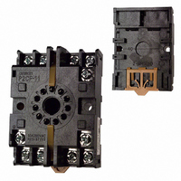
P2CF-11
Description
11 PIN Socket
Manufacturer
Omron
Type
Socketr
Specifications of P2CF-11
Number Of Positions
11
Mounting Type
DIN Rail
Termination Style
Screw Terminal
Accessory Type
Socket
Rohs Compliant
Yes
Associated Relay Series
H5CL
Number Of Poles
11
Mounting Style
DIN Rail
Lead Free Status / RoHS Status
Lead free / RoHS Compliant
For Use With/related Products
Multiple Series
For Use With
Z2998 - RELAY TIMER DGTL SPDT 100/240VACZ2366 - RELAY REPEAT CYCLE ANLG 30HRSZ997 - RELAY TIMER ANALOG 24VDC/ACZ2358 - RELAY REPEAT CYCLE ANLG 30HRSZ876 - RELAY TIMER DPDT ANALOG 120\240V
Lead Free Status / Rohs Status
Lead free / RoHS Compliant
Other names
P2CF11
Z884
Z884


J CHARACTERISTICS
Note: 1. The values are based on the set value.
Item
Repeat accuracy
Insulation resistance
Dielectric strength
Impulse withstand voltage
Noise immunity
Static immunity
Vibration resistance
Shock resistance
Ambient temperature
Ambient humidity
Service life
EMC
Materials
Weight
2. The value is applied for a minimum pulse width of 1 ms.
H5CL-Aj (AC models)
Power start: ±0.01% ±0.05 s max. (See Note 1.)
Signal start: ±0.005% ±0.03 s max. (See Note 1.)
Signal start, at transistor output model: ±0.005% ±3 ms max. (See Note 1 and 2.)
If the set value is within the sensor waiting time (250 ms max.) in the case of power start, the
control output of the H5CL will not be turned ON until the sensor waiting time passes.
100 MΩ min. (at 500 VDC) (between current-carrying terminal and exposed
non-current-carrying metal parts, and between non-continuous contacts)
2,000 VAC, 50/60 Hz for 1 min (between
current-carrying terminal and exposed
non-current-carrying metal parts)
1,000 VAC, 50/60 Hz for 1 min (between
non-continuous contacts)
3.0 kV (between power terminals)
4.5 kV (between current-carrying terminal and
exposed non-current-carrying metal parts)
±1.5 kV (between power terminals)
±600 V (between input terminals),
square-wave noise by noise simulator (pulse
width: 100 ns/1 µs, 1-ns rise)
Destruction: 15 kV
Malfunction: 8 kV
Destruction: 10 to 55 Hz, 0.75-mm single amplitude each in three directions
Malfunction: 10 to 55 Hz, 0.5-mm single amplitude each in three directions
Destruction: 294 m/s
Malfunction: 98 m/s
Operating: - -10 to 55°C (14 to 131°F) with no icing; if timers are mounted side-by-side: - -10 to
50°C (14 to 122°F) with no icing
Storage: - -25 to 65°C (- -13 to 149°F) with no icing
Operating: 35% to 85%
Mechanical: 10,000,000 operations min.
Electrical: 100,000 operations min. (3 A at 250 VAC, resistive load)
(EMI):
Emission Enclosure:
Emission AC Mains:
(EMS):
Immunity ESD:
Immunity RF-interference:
Immunity Conducted Disturbance: ENV50141:
Immunity Burst:
Case: plastic (Munsell 5Y7/1), light gray
Approx. 130 g
2
3
2
(10G) each in three directions
(30G) each in three directions
EN50081-2
EN55011 Group 1 class A
EN55011 Group 1 class A
EN50082-2
EN61000-4-2: 4 kV contact discharge (level 2)
ENV50140:
EN61000-4-4: 2 kV power-line (level 3)
H5CL-ADj (DC models)
1,000 VAC, 50/60 Hz for 1 min (between
current-carrying terminal and exposed
non-current-carrying metal parts, and
between non-continuous contacts)
1.0 kV (between power terminals)
1.5 kV (between current-carrying terminal and
exposed non-current-carrying metal parts)
±480 kV (between power terminals)
±600 V (between input terminals),
square-wave noise by noise simulator (pulse
width: 100 ns/1 µs, 1-ns rise)
Approx. 110 g
8 kV air discharge (level 3)
10 V/m (80 MHz to 1 GHz) (level 3)
10 V (0.15 to 80 MHz) (level 3)
2 kV I/O signal-line (level 4)
Related parts for P2CF-11
Image
Part Number
Description
Manufacturer
Datasheet
Request
R

Part Number:
Description:
SOCKET 8-PIN FOR H3CR-H
Manufacturer:
Omron
Datasheet:

Part Number:
Description:
SOCKET 11-PIN FOR H3CR-H
Manufacturer:
Omron
Datasheet:

Part Number:
Description:
8 PIN Socket
Manufacturer:
Omron
Datasheet:


Part Number:
Description:
G6S-2GLow Signal Relay
Manufacturer:
Omron Corporation
Datasheet:
Part Number:
Description:
Compact, Low-cost, SSR Switching 5 to 20 A
Manufacturer:
Omron Corporation
Datasheet:
Part Number:
Description:
Manufacturer:
Omron Corporation
Datasheet:
Part Number:
Description:
Manufacturer:
Omron Corporation
Datasheet:
Part Number:
Description:
Manufacturer:
Omron Corporation
Datasheet:
Part Number:
Description:
Manufacturer:
Omron Corporation
Datasheet: