M18TUP6E BANNER ENGINEERING, M18TUP6E Datasheet - Page 3
M18TUP6E
Manufacturer Part Number
M18TUP6E
Description
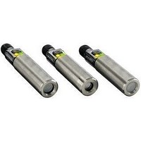
Infrared Temperature Sensor
Manufacturer
BANNER ENGINEERING
Datasheet
1.M18TUP14.pdf
(8 pages)
Specifications of M18TUP6E
Field Of View
6
Operating Temperature Range
-20°C To +70°C
Response Time
75ms
Sensing Face Type
Enclosed Plastic
Wavelength Typ
14µm
Rise Time
75ms
Opto Case Style
Module
Sensor Output
Voltage
Features
Enclosed Plastic Face


T-GAGE
M18T Series Temperature Sensors –
™
Analog Output
Apparent Temperature
Two factors that have a large influence on apparent temperature are the object’s emissivity
and whether or not the object fills the sensor’s field of view.
Object Emissivity: A “blackbody” is a “perfect” emitter, with an emissivity of 1.0 at all
temperatures and wavelengths. Most surfaces emit only a fraction of the amount of thermal
energy that a blackbody would. Typical T-GAGE applications will be sensing objects with
emissivities ranging from 0.5 to 0.95. Many references are available with tables of emissivity
coefficients for common materials. In general, shiny unpainted metals have low emissivity,
while non-glossy surfaces have high emissivity. Shiny surfaces: a mirror or shiny surface
can redirect an object’s emitted energy to an undesired location, or even bring additional
unintended thermal energy into the sensor’s field of view (see page 6).
Object Size: If the object being detected does not fill the sensor’s field of view, then the
sensor will average the temperature of that object and whatever else is in the sensing
field of view. For the sensor to collect the maximum amount of energy, the object should
completely fill the sensor’s field of view. However, in some applications, when the object is
too small, this may not be possible. In such cases, if the object is hot enough, the thermal
contrast may still be adequate to trigger the sensor’s output.
Analog Output
The T-GAGE analog sensor can be programmed for either positive or negative output slope,
based on the teach order (see Figure 3). If the cold limit is taught first, the slope will be
positive; if the hot limit is taught first, the slope will be negative. Banner’s scalable output
automatically distributes the output signal over the width of the programmed sensing
window.
Alarm Output
The alarm output will activate when the analog output is at 10V (see Figure 3).
Figure 3. Analog/Alarm outputs as a function
of taught conditions
Sensor Programming
Two TEACH methods may be used to program the sensor:
• Teach individual minimum and maximum limits (Two-Point Static Teach), or
• Dynamic Teach for on-the-fly programming.
The sensor may be programmed either via its push button, or via a remote switch. Remote
programming also may be used to disable the push button, preventing unauthorized
personnel from adjusting the programming settings. To access this feature, connect a
normally open switch between the sensor’s gray wire and dc common or connect the gray
wire to a digital input (PLC).
NOTE: The impedance of the Remote Teach input is 3 kΩ.
Programming is accomplished by following the sequence of input pulses (see programming
procedures starting on page 4). The duration of each pulse (corresponding to a push button
“click”), and the period between multiple pulses, are defined as “T”:
0.04 seconds < T < 0.8 seconds
Banner Engineering Corp.
Minneapolis, MN U.S.A.
•
www.bannerengineering.com • Tel: 763.544.3164
3
P/N 123698
Related parts for M18TUP6E
Image
Part Number
Description
Manufacturer
Datasheet
Request
R

Part Number:
Description:
Photoelectric Sensor
Manufacturer:
BANNER ENGINEERING
Datasheet:

Part Number:
Description:
Photoelectric Sensor
Manufacturer:
BANNER ENGINEERING
Datasheet:

Part Number:
Description:
LEDIR70XD4-XM-81039 MAX INTENS STROBE ONLY NO BANNER MARKS
Manufacturer:
BANNER ENGINEERING
Part Number:
Description:
M18SP6DL-72225 LABELED MOELLER NO BANNER MARKINGS BULK PACK
Manufacturer:
BANNER ENGINEERING
Part Number:
Description:
M18SP6DLQ-72226 LABLED MOELLER NO BANNER MARKINGS BULK PACK
Manufacturer:
BANNER ENGINEERING
Part Number:
Description:
M18SP6L-72223 LABELED MOELLER NO BANNER MARKINGS BULK PACK
Manufacturer:
BANNER ENGINEERING
Part Number:
Description:
M18SP6LQ-72224 LABELED MOELLER NO BANNER MARKINGS BULK PACK
Manufacturer:
BANNER ENGINEERING
Part Number:
Description:
P4D1-77908 P4 DRIVER GENERIC NO BANNER MARKINGS RESALE TO CUSTOMER
Manufacturer:
BANNER ENGINEERING
Part Number:
Description:
Photoelectric Sensor
Manufacturer:
BANNER ENGINEERING
Datasheet:

Part Number:
Description:
Programmable Indicator Light
Manufacturer:
BANNER ENGINEERING
Datasheet:
Part Number:
Description:
INDICATOR LED PANEL 50MM GRN/RED/YEL 30V
Manufacturer:
BANNER ENGINEERING
Datasheet:
Part Number:
Description:
Programmable Indicator Light
Manufacturer:
BANNER ENGINEERING
Datasheet: