M18TUP6E BANNER ENGINEERING, M18TUP6E Datasheet - Page 5
M18TUP6E
Manufacturer Part Number
M18TUP6E
Description
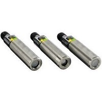
Infrared Temperature Sensor
Manufacturer
BANNER ENGINEERING
Datasheet
1.M18TUP14.pdf
(8 pages)
Specifications of M18TUP6E
Field Of View
6
Operating Temperature Range
-20°C To +70°C
Response Time
75ms
Sensing Face Type
Enclosed Plastic
Wavelength Typ
14µm
Rise Time
75ms
Opto Case Style
Module
Sensor Output
Voltage
Features
Enclosed Plastic Face


Banner Engineering Corp.
www.bannerengineering.com • Tel: 763.544.3164
...
...
• Not available via push button
• Not available via push button
• Push and hold push
• “Double-click”
• “Single-click”
button for 2 seconds
push button
push button
...
...
T
T
Push Button
Push Button
T-GAGE
Push Button
•
Minneapolis, MN U.S.A.
D
D
...
Dynamic TEACH Procedure
T
T
T
T
™
T
T
T
T
Procedure
Procedure
T
T
T
M18T Series Temperature Sensors –
T
T
T
2 seconds
The following procedure changes the direction of the analog output slope from negative to
positive or from positive to negative. See page 3 for an explanation of the analog output slope.
The push button lockout feature enables or disables the push button to prevent
unauthorized adjustment of the program settings.
Dynamic TEACH is a method of setting the sensor’s limits while the application is active.
Dynamic TEACH will sense the high and low temperature limits of the process and
automatically set the analog range between these limits.
The output slope will remain in the direction of the most recently taught Two-Point Static
TEACH or default to positive.
• Triple-pulse the remote line
T
• Four-pulse the remote line
T
• No action required
• Double-pulse the remote line
• Single-pulse the remote line
T
0.04 sec. < T < 0.8 sec
0.04 sec. < T < 0.8 sec
D
0.04 sec. < T < 0.8 sec.
Remote Line
T
T
T
Remote Line
or
T
T
T
T
Remote Line
or
T
T
T
T
T
T
T
T
T
T
T
T
T
2 seconds
T
T
T
T
Teaching Limits Using Dynamic TEACH
T
T
T
T
Changing Direction of Output Slope
T
2 seconds
T
T
.
.
T
T
T
Push Button Lockout
T
or
• Output slope changes to opposite of previous setting
T
T
T
• Push button is either enabled or disabled, depending on
T
T
previous condition.
T
• Power LED turns Red
• Alarm LED turns OFF
• Sensor begins dynamic learning process
• Alarm LED flashes Yellow @ 2 Hz
• Sensor ends data collection; sets 0V and 10V limits
• Power LED turns Green
• Sensor returns to Run mode
T
T
T
T
T
T
T
T
T
T
2 seconds
T
T
T
T
T
T
Result
Result
T
Result
T
T
T
Analog Output
P/N 123698
5
Related parts for M18TUP6E
Image
Part Number
Description
Manufacturer
Datasheet
Request
R

Part Number:
Description:
Photoelectric Sensor
Manufacturer:
BANNER ENGINEERING
Datasheet:

Part Number:
Description:
Photoelectric Sensor
Manufacturer:
BANNER ENGINEERING
Datasheet:

Part Number:
Description:
LEDIR70XD4-XM-81039 MAX INTENS STROBE ONLY NO BANNER MARKS
Manufacturer:
BANNER ENGINEERING
Part Number:
Description:
M18SP6DL-72225 LABELED MOELLER NO BANNER MARKINGS BULK PACK
Manufacturer:
BANNER ENGINEERING
Part Number:
Description:
M18SP6DLQ-72226 LABLED MOELLER NO BANNER MARKINGS BULK PACK
Manufacturer:
BANNER ENGINEERING
Part Number:
Description:
M18SP6L-72223 LABELED MOELLER NO BANNER MARKINGS BULK PACK
Manufacturer:
BANNER ENGINEERING
Part Number:
Description:
M18SP6LQ-72224 LABELED MOELLER NO BANNER MARKINGS BULK PACK
Manufacturer:
BANNER ENGINEERING
Part Number:
Description:
P4D1-77908 P4 DRIVER GENERIC NO BANNER MARKINGS RESALE TO CUSTOMER
Manufacturer:
BANNER ENGINEERING
Part Number:
Description:
Photoelectric Sensor
Manufacturer:
BANNER ENGINEERING
Datasheet:

Part Number:
Description:
Programmable Indicator Light
Manufacturer:
BANNER ENGINEERING
Datasheet:
Part Number:
Description:
INDICATOR LED PANEL 50MM GRN/RED/YEL 30V
Manufacturer:
BANNER ENGINEERING
Datasheet:
Part Number:
Description:
Programmable Indicator Light
Manufacturer:
BANNER ENGINEERING
Datasheet: