D4NL-1AFA-B Omron, D4NL-1AFA-B Datasheet - Page 14
D4NL-1AFA-B
Manufacturer Part Number
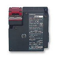
D4NL-1AFA-B
Description
SAFETY SWITCH
Manufacturer
Omron
Specifications of D4NL-1AFA-B
Contact Voltage Ac Max
240V
Contact Voltage Dc Max
24V
Contact Current Ac Max
10A
Contact Current Dc Max
200mA
Switch Terminals
Screw
Svhc
No SVHC (15-Dec-2010)
Approval Bodies
EN60747-5-1, IEC 947-5-1, EN1088,
Contact Configuration
SPST-NC / SPST-NO
Lead Free Status / Rohs Status
Lead free / RoHS Compliant


Precautions
Holding Force
• Do not apply a force exceeding the specified holding force. Doing
• Either install another locking component (e.g., a stop) in addition to
• The Switch contacts can be used for either standard loads or
• Turn OFF the power before disassembling the Switch or touching
• Mount the Operation Key in a location where it will not come in con-
• Do not impose excessive force on the Operation Key when it is
• Observe the specified insertion radius for the Operation Key and
• Do not use the Switch in starting circuits. (Use for safety confirma-
• When using the Switch in emergency-stop circuits or other safety
• In order to prevent short-circuit damage to the Switch, connect a
• Turn the power OFF when wiring. After wiring is completed, be sure
• In order to prevent burning due to overvoltage, insert a protective
• Do not use the Switch where explosive gas, flammable gas, or any
• Ensure that the load current does not exceed the rated current.
• Be sure to wire the terminals correctly.
• Be sure to evaluate the Switch under actual operating conditions
• Do not drop the package or the product. Do not disassemble inter-
14
Do not insert the Operation Key with the door open. The machine
may operate and damage may result.
Do not use metal connectors or conduits with this switch. Damage
to the broken conduit hole may cause electric shock.
Change the head direction after changing the release key to the
UNLOCK position. Do not change the head direction with the cov-
er removed. Failure to observe these points may result in Switch
malfunction or damage.
so may break the Switch and the machine may continue to operate.
the Switch, or use a warning sticker or an indicator showing the
lock status so that a force exceeding the specified holding force is
not applied.
microloads. Once a contact has been used to switch a standard
load, however, it cannot be used for a load of a smaller capacity.
Doing so may result in roughening of the contact surface and con-
tact reliability may be lost.
any internal parts. Not doing so may result in electric shock.
tact with users when the door is opened or closed. Otherwise,
injury may result.
inserted into the Switch or drop the Switch with the Operation Key
inserted. Otherwise, the Operation Key may be deformed or the
Switch may be broken.
insert it in a direction perpendicular to the key hole.
tion signals.)
circuits that have a direct impact on human lives, operate the NC
contacts that have a direct opening mechanism in direct opening
mode. For safety purposes, prevent easy removal by, for example,
mounting the Switch and Operation Key with one-way screws or
attaching a protective cover and warning label.
fuse to the Switch in series. Use a fuse with a breaking current of
1.5 to 2 times the rated current. To conform to EN ratings, use a
IEC269-compliant 10-A fuse type gI or gG.
to mount the cover before use.
fuse in the solenoid circuits.
other dangerous gas may be present.
after installation.
nal parts.
Safety Precautions
!Caution
!Caution
!Caution
Guard Lock Safety-door Switch
D4NL
Release Key
• The release key is used to unlock the Switch in case of emergency
• If the release key setting is changed from LOCK to UNLOCK using
• After setting the release key to UNLOCK in order to, for example,
• When the Switch is used for the door of a machine room to ensure
• Do not use the release key to start or stop machines.
• The auxiliary lock must only be released by authorized personnel.
• Do not impose a force exceeding 1 N·m on the release key screws.
• To prevent the release key from being used by unauthorized per-
Mounting
• Do not use the Switch as a stopper. To prevent the door from com-
• When the Switch is used for a hinged door at a location near to the
Solenoid Lock Models
The solenoid lock locks the door only when power is supplied to the
solenoid. Therefore, the door will be unlocked if the power supply to
the solenoid stops. Therefore, do not use solenoid lock models for
machines that may be operating and dangerous even after the
machine stops operating.
or if the power supply to the Switch stops.
an appropriate tool, the lock will be released and the safety door
can be opened (mechanical lock models only).
change the head direction or perform maintenance, be sure to
return it to LOCK setting before resuming operation.
the safety of people performing adjustment work inside, if the
release key is set to UNLOCK, the door will not be locked when the
door is closed and no power will be supplied to the equipment.
The release key may be damaged and may not operated properly.
sonnel, set it to LOCK and seal it with seal wax.
ing into contact with the flange of the Operation Key, be sure to
mount the Switch with a stopper as shown above.
hinged side, where the Operation Key’s insertion radius is compar-
atively small, if an attempt is made to open the door beyond the
lock position, the force imposed will be much larger than for loca-
tions far from the hinged side, and the lock may be damaged.
Operation Key
Stopper
Door
LOCK
UNLOCK
Set zone (0.5 to 3 mm)
Switch
Related parts for D4NL-1AFA-B
Image
Part Number
Description
Manufacturer
Datasheet
Request
R

Part Number:
Description:
Safety Limit Switch
Manufacturer:
Omron
Datasheet:
Part Number:
Description:
Door Switch, 1NC/1NO Slo
Manufacturer:
Omron
Datasheet:
Part Number:
Description:
Limit Switch
Manufacturer:
Omron
Datasheet:
Part Number:
Description:
G1/2,1NC/1NO,1NC,1NO,Plst,lck
Manufacturer:
Omron
Datasheet:
Part Number:
Description:
Interlock Switch
Manufacturer:
Omron
Datasheet:
Part Number:
Description:
Limit Switch
Manufacturer:
Omron
Datasheet:
Part Number:
Description:
Locking Interlock Switch
Manufacturer:
Omron
Datasheet:
Part Number:
Description:
Interlock Door Switch
Manufacturer:
Omron
Datasheet:
Part Number:
Description:
Safety Door Switch
Manufacturer:
Omron
Datasheet:
Part Number:
Description:
Safety Door Switch
Manufacturer:
Omron
Datasheet:
Part Number:
Description:
Basic / Snap Action / Limit Switches 2NC+2NC SOL lock
Manufacturer:
Omron
Datasheet:
Part Number:
Description:
Basic / Snap Action / Limit Switches 3NC+1NC/1NO Metal head SOL.RLS
Manufacturer:
Omron
Datasheet:
Part Number:
Description:
SAFETY SWITCH
Manufacturer:
Omron
Datasheet:
Part Number:
Description:
SAFETY INTERLOCK SWITCH
Manufacturer:
Omron
Datasheet: