TMC-IDX TRINAMIC, TMC-IDX Datasheet - Page 19
TMC-IDX
Manufacturer Part Number
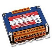
TMC-IDX
Description
DRIVE, STEPPER MOTOR, 3.5A
Manufacturer
TRINAMIC
Datasheet
1.TMC-IDX.pdf
(29 pages)
Specifications of TMC-IDX
Supply Voltage Range
12VDC To 48VDC
Output Current
3.5A
Current Limit Max
5A
External Depth
23mm
External Length / Height
63mm
External Width
63mm
Load Current
3.5A
No. Of Output Channels
2
Supply
RoHS Compliant
Svhc
No SVHC (15-Dec-2010)
Rohs Compliant
Yes


6.2.1.1 Examples for test move
6.2.1.2 Motor Current (C)
The motor current can be set by the user. To do this use the RS485 command “AC” in addition with a
percent value. To calculate the actual setting, please use the 100% values as shown in the table.
Internally the current is regulated by two independent parameters for the best module/motor
performance possible.
For chopper mode 2, the maximum setting is about 75% to 90% - at higher settings, motor microstep
behaviour may become harsh. The actual maximum depends upon the actual motor. This is to avoid
the motor coil current raising above the 100% setting at any time. Not all currents can be continuously
driven at all supply voltages / cooling circumstances. Please refer to motor current limitations.
*) Not possible for chopper mode 2.
6.2.1.3 Failure Readout (E)
The IDX provides a full driver failure analysis in SPI mode (8 Bit). The returned bit assignments are as
follows:
Bit
In the other two modes the failure analysis consists of only one bit:
Copyright © 2005, TRINAMIC Motion Control GmbH & Co. KG
7
6
5
4
3
2
1
0
•
•
•
•
Name
OT
OTPW
UV
OCHS
OLB
OLA
OCB
OCA
AA 500, AV 50000, AV –50000 ⇒ try other AA 100…8000, AV 0…400000
AA 500, AV 50000, AC 255 ⇒ test torque manually ⇒ AC 50 ⇒ test torque
AV 0, AA 500, AV 50000,
AR, AP 0, AR, AA 500, AV 50000, AR
1: short circuit or overtemperature
0: no failure
Different accelerations and velocities
Max. current – test of torque
Coil current change
Read and set position
100
AC
75
66
50
33
25
10
Function
Overtemperature
temperature prewarning
driver undervoltage
overcurrent high side
open load bridge B
open load bridge B
overcurrent bridge B low side
overcurrent bridge A low side
Table 6.2: Motor Current Examples for IDX / IDX 4803
IDX 7505
I
0.71A
COIL,PP
7.1A
5.3A
4.7A
3.5A
2.4A
1.8A
Table 6.3: Failure readout in SPI mode
IDX 7505
I
COIL,RMS
AC 200, AI 0 (100%), AI 18 (50%), AI 45 (33%), AI 63 (25%)
AC 100, AI 0, AI 18, AI 45, AI 63
1.26A
0.50A
5.0A
3.8A
3.3A
2.5A
1.7A
Remark
“1” = driver chip off due to overtemperature
“1” = driver chip prewarning temperature exceeded
“1” = undervoltage on VS – does not cover all cases
(not available in current hardware implementation)
Open load detection can occur at fast motion also.
Open load detection can occur at fast motion also.
Short circuit detected. Please check motor wiring.
Short circuit detected. Please check motor wiring.
IDX 4803
I
COIL,PP
4.8A
3.6A
3.2A
2.4A
1.6A
1.2A
0.5A
IDX 4803
I
COIL,RMS
0.85A
0.35A
3.4A
2.6A
2.2A
1.7A
1.1A
% to max.
100% *)
75%
66%
50%
33%
25%
10%
I
COIL
Related parts for TMC-IDX
Image
Part Number
Description
Manufacturer
Datasheet
Request
R

Part Number:
Description:
CONTROLLER, STEPPER MOTOR, AMPLIF
Manufacturer:
TRINAMIC
Datasheet:

Part Number:
Description:
57mm/NEMA23 or 60mm/NEMA24 Stepper Motor with Controller/Driver with Encoder and Serial Interface
Manufacturer:
TRINAMIC [TRINAMIC Motion Control GmbH & Co. KG.]
Datasheet:
Part Number:
Description:
60mm/NEMA24 Stepper Motor with Controller/Driver, with Encoder and Serial Interface
Manufacturer:
TRINAMIC [TRINAMIC Motion Control GmbH & Co. KG.]
Datasheet:
Part Number:
Description:
42mm/NEMA17 Stepper Motor with Controller/Driver, Encoderand Serial Interface
Manufacturer:
TRINAMIC [TRINAMIC Motion Control GmbH & Co. KG.]
Datasheet:
Part Number:
Description:
42mm/NEMA17 High Performance BLDC Motor with Controller/Driver and Serial Interface
Manufacturer:
TRINAMIC [TRINAMIC Motion Control GmbH & Co. KG.]
Datasheet:

Part Number:
Description:
57mm diameter BLDC Encoder Motor with Controller/Driver and Serial Interface
Manufacturer:
TRINAMIC [TRINAMIC Motion Control GmbH & Co. KG.]
Datasheet:
Part Number:
Description:
57mm / NEMA23 Stepper Motor with Controller / Driver and Serial Interface
Manufacturer:
TRINAMIC [TRINAMIC Motion Control GmbH & Co. KG.]
Datasheet:
Part Number:
Description:
42mm / NEMA17 Stepper Motor with Controller / Driver and Serial Interface
Manufacturer:
TRINAMIC [TRINAMIC Motion Control GmbH & Co. KG.]
Datasheet:
