TMC-IDX TRINAMIC, TMC-IDX Datasheet - Page 28
TMC-IDX
Manufacturer Part Number
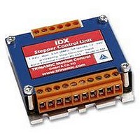
TMC-IDX
Description
DRIVE, STEPPER MOTOR, 3.5A
Manufacturer
TRINAMIC
Datasheet
1.TMC-IDX.pdf
(29 pages)
Specifications of TMC-IDX
Supply Voltage Range
12VDC To 48VDC
Output Current
3.5A
Current Limit Max
5A
External Depth
23mm
External Length / Height
63mm
External Width
63mm
Load Current
3.5A
No. Of Output Channels
2
Supply
RoHS Compliant
Svhc
No SVHC (15-Dec-2010)
Rohs Compliant
Yes


6.6 Option: Pseudo DC-Motor mode (not supported by
The velocity of the motor in this mode is
changed through a constant voltage at the
General Purpose input. The operational
voltage is 7...48V. This option may be
available in a future firmware version.
6.6.1 Setting up the module
It is advised to connect an external voltage
divider to the GPI pin, as depicted.
However, there are two free places for 0805 SMD resistors to be equipped directly on the module IDX.
To enable this mode solder use resistors as follows:
Attention:
6.6.2 Parameterizing with RS485
First set Parameters for minimum voltage, maximum voltage and a zero point in between. Other
values can be changed also like max. acceleration, max. velocity, microsteps,…
Before enabling this mode with the RS485 command
Purpose Input (GPI). The voltage has to exceed zero point voltage before the regulation works.
6.6.3 Motion Control
Change the voltage at GPI between 7…48V. The motor will accelerate and decelerate relative to the
specified zero point. Additional parameters like resolutions of microsteps can be stored in the
EEPROM.
Copyright © 2005, TRINAMIC Motion Control GmbH & Co. KG
7V...V
software yet)
S
Do not try to make changes on the board until you are absolutely sure.
GND
+V
making changes on board:
S
be absolutely sure before
Figure 6.7: Layout Changes for DC-Motor option
R = 120k
R = 2.2k
GPI
…
connect a voltage of 7…48V to General
Figure 6.6: GPI wiring scheme
free Pads for 2.2k and 120k
IC
T
mounting hole
IC
IC
connector RM 3.5
T
T
D
ATM
168
D
D
Related parts for TMC-IDX
Image
Part Number
Description
Manufacturer
Datasheet
Request
R

Part Number:
Description:
CONTROLLER, STEPPER MOTOR, AMPLIF
Manufacturer:
TRINAMIC
Datasheet:

Part Number:
Description:
57mm/NEMA23 or 60mm/NEMA24 Stepper Motor with Controller/Driver with Encoder and Serial Interface
Manufacturer:
TRINAMIC [TRINAMIC Motion Control GmbH & Co. KG.]
Datasheet:
Part Number:
Description:
60mm/NEMA24 Stepper Motor with Controller/Driver, with Encoder and Serial Interface
Manufacturer:
TRINAMIC [TRINAMIC Motion Control GmbH & Co. KG.]
Datasheet:
Part Number:
Description:
42mm/NEMA17 Stepper Motor with Controller/Driver, Encoderand Serial Interface
Manufacturer:
TRINAMIC [TRINAMIC Motion Control GmbH & Co. KG.]
Datasheet:
Part Number:
Description:
42mm/NEMA17 High Performance BLDC Motor with Controller/Driver and Serial Interface
Manufacturer:
TRINAMIC [TRINAMIC Motion Control GmbH & Co. KG.]
Datasheet:

Part Number:
Description:
57mm diameter BLDC Encoder Motor with Controller/Driver and Serial Interface
Manufacturer:
TRINAMIC [TRINAMIC Motion Control GmbH & Co. KG.]
Datasheet:
Part Number:
Description:
57mm / NEMA23 Stepper Motor with Controller / Driver and Serial Interface
Manufacturer:
TRINAMIC [TRINAMIC Motion Control GmbH & Co. KG.]
Datasheet:
Part Number:
Description:
42mm / NEMA17 Stepper Motor with Controller / Driver and Serial Interface
Manufacturer:
TRINAMIC [TRINAMIC Motion Control GmbH & Co. KG.]
Datasheet:
