TMC-IDX TRINAMIC, TMC-IDX Datasheet - Page 2
TMC-IDX
Manufacturer Part Number
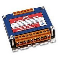
TMC-IDX
Description
DRIVE, STEPPER MOTOR, 3.5A
Manufacturer
TRINAMIC
Datasheet
1.TMC-IDX.pdf
(29 pages)
Specifications of TMC-IDX
Supply Voltage Range
12VDC To 48VDC
Output Current
3.5A
Current Limit Max
5A
External Depth
23mm
External Length / Height
63mm
External Width
63mm
Load Current
3.5A
No. Of Output Channels
2
Supply
RoHS Compliant
Svhc
No SVHC (15-Dec-2010)
Rohs Compliant
Yes


Table of Contents
1
2
3
4
5
6
7
Copyright © 2005, TRINAMIC Motion Control GmbH & Co. KG
3.1
3.2
3.3
4.1
4.2
5.1
5.2
5.3
5.4
5.5
6.1
6.2
6.3
6.4
6.5
6.6
7.1
7.2
Features ........................................................................................................................................... 4
Life support policy ............................................................................................................................ 5
Electrical and Mechanical Interfacing............................................................................................... 6
Operational Ratings ......................................................................................................................... 8
Getting Started ............................................................................................................................... 11
5.1.1
5.5.1
5.5.2
Functional Description.................................................................................................................... 17
6.2.1
6.2.2
6.3.1
6.3.2
6.6.1
6.6.2
6.6.3
Revision History ............................................................................................................................. 29
5.1.1.1
5.1.1.2
5.1.1.3
6.2.1.1
6.2.1.2
6.2.1.3
6.2.1.4
6.2.1.5
6.2.1.6
6.2.1.7
6.2.1.8
6.2.1.9
6.2.1.10 Store Parameters to EEPROM (W) ............................................................................ 22
6.2.1.11 Microstep Resolution (Z)............................................................................................. 22
6.2.2.1
6.2.2.2
6.2.2.3
6.2.2.4
6.2.2.5
Pinning ...................................................................................................................................... 6
Dimensions ............................................................................................................................... 7
Connectors................................................................................................................................ 7
Practical maximum motor current ratings ................................................................................. 9
Step, Direction and Disable Inputs.......................................................................................... 10
Motor ....................................................................................................................................... 11
Connecting Motor and Power Supply ..................................................................................... 14
Power Supply Requirements .................................................................................................. 14
Connections for Step / Direction- Mode.................................................................................. 15
Connections for RS485 Interface............................................................................................ 16
Disable Function ..................................................................................................................... 17
RS485 Control Interface ......................................................................................................... 17
Step / Direction........................................................................................................................ 25
Reset to factory default ........................................................................................................... 26
Firmware Update..................................................................................................................... 27
Option: Pseudo DC-Motor mode (not supported by software yet).......................................... 28
Documentation Revision ......................................................................................................... 29
Firmware Revision .................................................................................................................. 29
Motor Choice...................................................................................................................... 11
Interface installation ........................................................................................................... 16
Control with terminal program............................................................................................ 16
RS485 Commands............................................................................................................. 18
Chopper Modes ................................................................................................................. 22
Direction ............................................................................................................................. 25
Step.................................................................................................................................... 26
Setting up the module ........................................................................................................ 28
Parameterizing with RS485 ............................................................................................... 28
Motion Control.................................................................................................................... 28
Motor velocity.............................................................................................................. 11
Chopper Modes 0 (SPI / Default Mode) and 1 (PWM) ............................................... 11
Chopper Mode 2 (PHASE) ......................................................................................... 12
Examples for test move .............................................................................................. 19
Motor Current (C)........................................................................................................ 19
Failure Readout (E)..................................................................................................... 19
StallGuard (G)............................................................................................................. 20
Limit Switch (L) ........................................................................................................... 20
Output setting (O) ....................................................................................................... 20
I/Os Readout (Q)......................................................................................................... 21
Baud Rate (U) ............................................................................................................. 21
Velocity Mode (V)........................................................................................................ 21
Chopper Mode 0 (SPI) / Default Mode ....................................................................... 22
Chopper Mode 1 (PWM)............................................................................................. 23
Chopper Mode 2 (PHASE) ......................................................................................... 23
Chopper mode 3 (Phase and SPI).............................................................................. 24
Chopper mode 4 (PWM and SPI) ............................................................................... 24
Related parts for TMC-IDX
Image
Part Number
Description
Manufacturer
Datasheet
Request
R

Part Number:
Description:
CONTROLLER, STEPPER MOTOR, AMPLIF
Manufacturer:
TRINAMIC
Datasheet:

Part Number:
Description:
57mm/NEMA23 or 60mm/NEMA24 Stepper Motor with Controller/Driver with Encoder and Serial Interface
Manufacturer:
TRINAMIC [TRINAMIC Motion Control GmbH & Co. KG.]
Datasheet:
Part Number:
Description:
60mm/NEMA24 Stepper Motor with Controller/Driver, with Encoder and Serial Interface
Manufacturer:
TRINAMIC [TRINAMIC Motion Control GmbH & Co. KG.]
Datasheet:
Part Number:
Description:
42mm/NEMA17 Stepper Motor with Controller/Driver, Encoderand Serial Interface
Manufacturer:
TRINAMIC [TRINAMIC Motion Control GmbH & Co. KG.]
Datasheet:
Part Number:
Description:
42mm/NEMA17 High Performance BLDC Motor with Controller/Driver and Serial Interface
Manufacturer:
TRINAMIC [TRINAMIC Motion Control GmbH & Co. KG.]
Datasheet:

Part Number:
Description:
57mm diameter BLDC Encoder Motor with Controller/Driver and Serial Interface
Manufacturer:
TRINAMIC [TRINAMIC Motion Control GmbH & Co. KG.]
Datasheet:
Part Number:
Description:
57mm / NEMA23 Stepper Motor with Controller / Driver and Serial Interface
Manufacturer:
TRINAMIC [TRINAMIC Motion Control GmbH & Co. KG.]
Datasheet:
Part Number:
Description:
42mm / NEMA17 Stepper Motor with Controller / Driver and Serial Interface
Manufacturer:
TRINAMIC [TRINAMIC Motion Control GmbH & Co. KG.]
Datasheet:
