MCBACIP CARLO GAVAZZI, MCBACIP Datasheet - Page 3
MCBACIP
Manufacturer Part Number
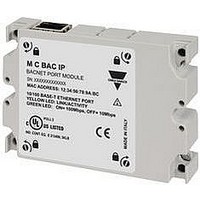
MCBACIP
Description
BACNET-IP PORT MODULE
Manufacturer
CARLO GAVAZZI
Datasheet
1.MC485232.pdf
(17 pages)
Specifications of MCBACIP
Accessory Type
BACNet-IP Port Module
For Use With
WM3096 Type Smart Modular Power Analyzer


Input specifications
WM30 96
Specifications are subject to change without notice
Rated inputs
Accuracy (Display + RS485)
(@25°C ±5°C, R.H.
≤60%, 48 to 62 Hz)
Current type
Current range (by CT)
Voltage (by direct connection
or VT/PT)
AV4 model
AV5 model
AV6 model
AV7 model
Current AV4, AV5, AV6,
AV7 models
Phase-neutral voltage
Phase-phase voltage
Frequency
Active and Apparent power
Power Factor
Reactive power
Active energy
Reactive energy
Start up current AV5, AV6
Start up current AV4, AV7
System type: 1, 2 or 3-
phase
Galvanic insulation by
means of built-in CT’s
AV4 and AV7: 1(2)A
AV4, AV5: 400/690VLL;
AV6, AV7: 100/208VLL
In: see below, Un: see
below
In: 1A, Imax: 2A; Un: 160
to 480VLN (277 to 830VLL)
In: 5A, Imax: 6A; Un: 160
to 480VLN (277 to 830VLL)
In: 5A, Imax: 6A; Un: 40 to
144VLN (70 to 250VLL)
In: 1A, Imax: 2A; Un: 40 to
144VLN (70 to 250VLL)
From 0.01In to 0.05In:
±(0.5% RDG +2DGT)
From 0.05In to Imax:
±(0.2% RDG +2DGT)
In the range Un: ±(0,2%
RDG +1DGT)
In the range Un: ±(0.5%
RDG +1DGT)
±0.1Hz (45 to 65Hz)
0.01In to 0.05In, PF 1:
±(1%RDG+1DGT)
From 0.05In to Imax
PF 0.5L, PF1, PF0.8C:
±(0.5%RDG+1DGT)
±[0.001+0.5% (1.000 - “PF
RDG”)]
0.5L/C: ±(1%RDG+1DGT)
0.05In to 0.1In, senφ
0.5L/C:
±(1.5%RDG+1DGT)
0.05In to Imax, senφ 1:
±(1%RDG+1DGT)
0.02In to 0.05In, senφ 1:
±(1.5%RDG+1DGT)
Class 0.5 according to
EN62053-22, ANSI C12.20
Class C according to
EN50470-3.
Class 1 according to
EN62053-23, ANSI C12.1.
AV5 and AV6: 5(6)A
5mA
1mA
0.1In to Imax, senφ
WM30 96 DS 271109
Energy additional errors
Influence quantities
Total Harmonic Distortion (THD)
Temperature drift
Sampling rate
Measurements
Crest factor
Current Overloads
Voltage Overloads
Input impedance
Frequency
Method
Coupling type
Continuous (AV5 and AV6)
Continuous (AV4 and AV7)
For 500ms (AV5 and AV6)
For 500ms (AV4 and AV7)
Continuous
For 500ms
400VL-L (AV4 and AV5)
208VL-L (AV6 and AV7)
5(10)A (AV5 and AV6)
1(2)A (AV4 and AV7)
According to EN62053-22,
ANSI C12.20,
Class B or C according to
EN50470-3, EN62053-23,
ANSI C12.1
±1% FS (FS: 100%)
AV4: Imin: 5mARMS; Imax:
15Ap; Umin: 30VRMS;
Umax: 585Vp
AV5: Imin: 5mARMS; Imax:
15Ap; Umin: 30VRMS;
Umax: 585Vp
AV6: Imin: 5mARMS; Imax:
15Ap; Umin: 30VRMS;
Umax: 585Vp
AV7: Imin: 5mARMS; Imax:
15Ap; Umin: 30VRMS;
Umax: 585Vp
≤200ppm/°C
3200 samples/s @ 50Hz,
3840 samples/s @ 60Hz
See “List of the variables
that can be connected to:”
TRMS measurements of
distorted wave forms.
By means of CT’s
AV5, AV6: ≤3 (15A max.
peak)
AV4, AV7: ≤3 (3A max.
peak)
6A, @ 50Hz
2A, @ 50Hz
120A, @ 50Hz
40A, @ 50Hz
1.2 Un
2 Un
> 1.6MΩ
> 1.6MΩ
< 0.2VA
< 0.2VA
40 to 440 Hz
3
Related parts for MCBACIP
Image
Part Number
Description
Manufacturer
Datasheet
Request
R

Part Number:
Description:
MAGNETIC CYLINDRICAL PROX. SENSOR
Manufacturer:
CARLO GAVAZZI
Datasheet:
Part Number:
Description:
CYLINDRICAL MAGNETIC SENSOR
Manufacturer:
CARLO GAVAZZI
Datasheet:
Part Number:
Description:
MAGNETIC CYLINDRICAL PROX. SENSOR
Manufacturer:
CARLO GAVAZZI
Datasheet:
Part Number:
Description:
Current and Voltage Controls / Current Transformer / 3-Phase
Manufacturer:
Carlo Gavazzi
Datasheet:

Part Number:
Description:
Definite Purpose Contactor
Manufacturer:
CARLO GAVAZZI
Datasheet:
Part Number:
Description:
Definite Purpose Contactor
Manufacturer:
CARLO GAVAZZI
Datasheet: