PAXCK000 Red Lion Controls, PAXCK000 Datasheet - Page 23
PAXCK000
Manufacturer Part Number
PAXCK000
Description
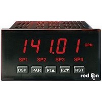
Digital Multifunction Timer
Manufacturer
Red Lion Controls
Type
Clock/Timerr
Datasheet
1.PAXTM000.pdf
(28 pages)
Specifications of PAXCK000
Time Range
0.001sec To 1hr
Power Consumption
18VA
Supply Voltage Ac, Min
85V
Signal Input Type
Pulse
Supply Voltage Max
250VAC
Time Range Max
999999h
Character Size
0.56"
Accuracy
±0.01% %
Connection Type
Cage-Clamp
Cut Out, Panel
3.62×1.77 "
Digit Height
0.56
Dimensions
4.2"L×3.8"W×1.95"H
Display Digit Height
0.56 "
Display Resolution
0.001 Sec. (Minimum Digit), 1 hr. (Single Digit)
Display Type
LED
Function
Real Time Clock/Timer
Humidity
0 to 85% (Max.) RH
Isolation Voltage
2300 V (RMS)
Length, Stripping
0.3 in. Wire
Memory Type
Non-Volatile EEPROM
Number Of Digits
6
Power, Rating
18 VA
Primary Type
Electronic
Range, Measurement
0 to 999999
Special Features
Programmable Function Keys
Standards
cULus Listed, CSA Certified
Temperature, Operating
0 to +50 °C
Termination
Cage Clamp
Torque
4.5 in.-lbs
Voltage, Range
85 to 250 VAC
Voltage, Supply
85 to 250 VAC
Four Separate Displays
Timer, Counter, Real-Time Clock and Date
Display Font Color
Red
No. Of Digits / Alpha
6
Supply Voltage Ac, Max
250V
Rohs Compliant
NA
Lead Free Status / RoHS Status
na


COMMUNICATION FORMAT
In serial communications, the voltage is switched between a high and low level
at a predetermined rate (baud rate) using ASCII encoding. The receiving device
reads the voltage levels at the same intervals and then translates the switched
levels back to a character.
lists the voltage levels for each standard.
characters. Each ASCII character is “framed” with a beginning start bit, an
optional parity bit and one or more ending stop bits. The data format and baud
rate must match that of other equipment in order for communication to take
place. The figures list the data formats employed by the meter.
and Time Parameters. In the Display Mode, the DAT annunciator indicates the
RTC Date is currently being shown. The RTC Time display is shown with no
annunciator. This programming module can only be accessed if a Real-Time
Clock card is installed.
display the sub-menu where the Time can be set or changed. The RTC Time is
entered in “Hours-Minutes”, 12-hour format, with AM/PM indication. When
the
“Seconds” always start from 00 when the Time is entered. Select
to the next parameter without changing the Time.
6.8 MODULE 8 - R
* Voltage levels at the Receiver
Data is transferred from the meter through a serial communication channel.
The voltage level conventions depend on the interface standard. The table
LOGIC
Data is transmitted one byte at a time with a variable idle period between
Module 8 is the programming module for the Real-Time Clock (RTC) Date
This parameter sets the Time for the Real-Time Clock. Selecting
PAR
1
0
key is pressed, the new Time is entered and begins running. The
INTERFACE STATE
space (active)
mark (idle)
Character Frame Figure
HOURS-MINUTES Am/Pm
TXD,RXD; +3 to +25 V
TXD,RXD; -3 to -25 V
SET TIME
RS232*
EAL
-T
a-b > +200 mV
a-b < -200 mV
RS485*
IME
PARAMETER MENU
to advance
C
will
LOCK
23
Start Bit and Data Bits
receiving device to prepare for reception of data. One bit period later, the least
significant bit of the ASCII encoded character is transmitted, followed by the
remaining data bits. The receiving device then reads each bit position as they
are transmitted.
Parity Bit
a zero or a one, so that the total number of ones contained in the transmission
(including the parity bit) is either even or odd. This bit is used by the receiver
to detect errors that may occur to an odd number of bits in the transmission.
However, a single parity bit cannot detect errors that may occur to an even
number of bits. Given this limitation, the parity bit is often ignored by the
receiving device. The PAX meter ignores the parity bit of incoming data and
sets the parity bit to odd, even or none (mark parity) for outgoing data.
Stop Bit
period pause to allow the receiver to prepare to re-synchronize to the start of a
new transmission (start bit of next byte). The receiver then continuously looks
for the occurrence of the start bit. If 7 data bits and no parity is selected, then 2
stop bits are sent from the PAX.
display the sub-menu where the Date can be set or changed. The RTC Date is
entered in “Month.Day.Year” format (two-digit values). When the
pressed, the new Date is entered. Select
without changing the Date.
Data transmission always begins with the start bit. The start bit signals the
After the data bits, the parity bit is sent. The transmitter sets the parity bit to
The last character transmitted is the stop bit. The stop bit provides a single bit
This parameter sets the Date for the Real-Time Clock. Selecting
Set the Day of the week for the Real-Time Clock.
P
ARAMETERS
MONTH.DAY.YEAR
SET DATE
SET DAY
(
to advance to the next parameter
) - PAXCK
PAR
key is
will
Related parts for PAXCK000
Image
Part Number
Description
Manufacturer
Datasheet
Request
R

Part Number:
Description:
Counter
Manufacturer:
Red Lion Controls
Datasheet:
Part Number:
Description:
Miniature Length Sensor
Manufacturer:
Red Lion Controls
Datasheet:
Part Number:
Description:
Model Lsc - Single Channel Output Length Sensor
Manufacturer:
Red Lion Controls
Datasheet: