3RV19011A SIEMENS, 3RV19011A Datasheet - Page 32
3RV19011A
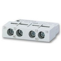
Manufacturer Part Number
3RV19011A
Description
AUXILIARY SWITCH, LATERALLY FIT
Manufacturer
SIEMENS
Datasheet
1.3RV19011A.pdf
(56 pages)
Specifications of 3RV19011A
Approval Bodies
UL, CSA, VDE
Contact Configuration
1 N/C + 1 N/O
No. Of Poles
2
Terminal Type
Screw
Accessory Type
Lateral Auxilary Contact
For Use With
-000 A


General data
1) Exception: up to size S3, only stand-alone installation is possible.
2) Alternatively available for screw connection.
Features
Short-circuit strength up to 100 kA
at 690 V
(in conjunction with the corresponding
fuses or the corresponding motor starter
protector)
Electrical and mechanical matching
to 3RT1 contactors
Straight-through transformers for
main circuit
(in this case the cables are routed
through the push-through openings of
the overload relay and connected
directly to the box terminals of the
contactor)
Spring-loaded terminal connection
system for main circuit
Spring-loaded terminal connection
system for auxiliary circuits
Temperature compensation
Very high long-term stability
Wide setting ranges
Trip class CLASS 5
Trip class > CLASS 10
Low power loss
Design of load feeders
Other features
5/32
Overload Relays
2)
Siemens LV 1 · 2006
2)
2)
Benefits
• Provides optimum protection of the loads and
• Simplifies configuration
• Reduces wiring overhead and costs
• Enables stand-alone installation as well as
• Reduces contact resistance
• Saves wiring costs (easy, no need for tools,
• Saves material costs
• Reduces installation costs
• Enables fast connections
• Permits vibration-resistant connections
• Enables maintenance-free connections
• Enables fast connections
• Permits vibration-resistant connections
• Enables maintenance-free connections
• Allows the use of the relays at high temperatures
• Prevents premature tripping
• Allows compact installation of the controlgear
• Simplifies configuration
• Enables space to be saved in the controlgear
• Provides safe protection for the loads even after
• Reduce the number of variants
• Minimize the engineering outlay and costs
• Minimize storage overhead, storage costs,
• Enables solutions for very fast starting motors
• Enables heavy starting solutions
• Reduces power consumption and energy costs
• Minimizes temperature rises of the contactor and
• Direct mounting to contactor saves space, even
operating personnel in the event of short-circuits
due to insulation faults or faulty switching
operations
space-saving direct mounting
(only one point of contact)
and fast).
without derating
cabinet without space between the units/load
feeders
cabinet
years of use in severe operating conditions
tied-up capital
requiring special protection (e.g. Ex motors)
(up 98% less power is used than for thermal
overload relays).
controlgear cabinet – in some cases this may
eliminate the need for controlgear cabinet cooling.
for high motor currents (i.e. no heat decoupling is
required).
3RU11
(S00)
(✔)
✔
✔
✔
✔
✔
--
--
--
--
--
3RB20/3RB21
(only 3RB21)
(S2 ... S6)
(1:4)
✔
✔
✔
✔
✔
✔
✔
✔
✔
✔
--
3RB22/3RB23
(S00 ... S6)
(1:10)
✔
✔
✔
✔
✔
✔
✔
✔
✔
✔
--
1)
Related parts for 3RV19011A
Image
Part Number
Description
Manufacturer
Datasheet
Request
R

Part Number:
Description:
Intel 80C32 - Siemens SAB-C501, Nearest Equivalent Replacement
Manufacturer:
Siemens Semiconductor Group
Part Number:
Description:
IGBT MODULE
Manufacturer:
Siemens Semiconductor Group
Datasheet:
Part Number:
Description:
SIMOPAC Module (Power module Single switch N channel Enhancement mode)
Manufacturer:
Siemens Semiconductor Group
Datasheet:
Part Number:
Description:
(BSMxxx) TRANSISTOR
Manufacturer:
Siemens Semiconductor Group
Datasheet:
Part Number:
Description:
SIMOPAC Module (Power module Single switch N channel Enhancement mode)
Manufacturer:
Siemens Semiconductor Group
Datasheet:
Part Number:
Description:
main ratings
Manufacturer:
Siemens Semiconductor Group
Datasheet:
Part Number:
Description:
Manufacturer:
Siemens Semiconductor Group
Datasheet:
Part Number:
Description:
Manufacturer:
Siemens Semiconductor Group
Datasheet:
Part Number:
Description:
Manufacturer:
Siemens Semiconductor Group
Datasheet:
Part Number:
Description:
ICs for Consumer Electronics
Manufacturer:
Siemens Semiconductor Group
Datasheet:
Part Number:
Description:
Video and Sound IF with V & S SCART
Manufacturer:
Siemens Semiconductor Group
Datasheet:
Part Number:
Description:
Manufacturer:
Siemens Semiconductor Group
Datasheet:
Part Number:
Description:
Multistandard Sound IF
Manufacturer:
Siemens Semiconductor Group
Datasheet:
Part Number:
Description:
MULTISTANDARD AM FM SOUND IF IC
Manufacturer:
Siemens Semiconductor Group
Datasheet: