3RV19011A SIEMENS, 3RV19011A Datasheet - Page 9
3RV19011A
Manufacturer Part Number
3RV19011A
Description
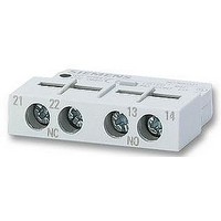
AUXILIARY SWITCH, LATERALLY FIT
Manufacturer
SIEMENS
Datasheet
1.3RV19011A.pdf
(56 pages)
Specifications of 3RV19011A
Approval Bodies
UL, CSA, VDE
Contact Configuration
1 N/C + 1 N/O
No. Of Poles
2
Terminal Type
Screw
Accessory Type
Lateral Auxilary Contact
For Use With
-000 A


■
Selection and ordering data
Without auxiliary switches
1) Standard value for 4-pole standard motors at 50 Hz 400 V AC. The actual
2) For overload protection of the motors, appropriate overload relays must
* You can order this quantity or a multiple thereof.
Size S0
Size S2
Size S3
Size S3, with increased switching capacity
starting and rated data of the motor to be protected must be considered
when selecting the units.
be used.
Rated
current
I
A
0.16
0.2
0.25
0.32
0.4
0.5
0.63
0.8
1
1.25
1.6
2
2.5
3.2
4
5
6.3
8
10
12.5
16
20
22
25
16
20
25
32
40
45
50
40
50
63
75
90
100
16
20
25
32
40
50
63
75
90
100
n
Suitable
for three-
phase
induction
motors
with P
kW
0.04
0.06
0.06
0.09
0.09
0.12
0.18
0.18
0.25
0.37
0.55
0.75
0.75
1.1
1.5
1.5
2.2
3
4
5.5
7.5
7.5
11
11
7.5
7.5
11
15
18.5
22
22
18.5
22
30
37
45
45
7.5
7.5
11
15
18.5
22
30
37
45
45
1)
Setting range
for thermal
overload
release
A
None
None
None
None
None
None
None
None
None
None
None
None
None
None
None
None
None
None
None
None
None
None
None
None
None
None
None
None
None
None
None
None
None
None
None
None
None
None
None
None
None
None
None
None
None
None
None
2)
Instan-
taneous
over-
current
release
A
2.1
2.6
3.3
4.2
5.2
6.5
8.2
10
13
16
21
26
33
42
52
65
82
104
130
163
208
260
286
325
208
260
325
416
520
585
650
520
650
819
975
1170
1235
208
260
325
416
520
650
819
975
1170
1235
I
3RV Motor Starter Protectors up to 100 A
Short-circuit
breaking
capacity
at
400 V AC
I
kA
100
100
100
100
100
100
100
100
100
100
100
100
100
100
100
100
100
100
100
100
50
50
50
50
50
50
50
50
50
50
50
50
50
50
50
50
50
100
100
100
100
100
100
100
100
100
100
cu
DT Screw connection
A
A
A
A
A
A
A
A
A
A
A
A
A
A
A
A
A
A
A
A
A
A
A
A
A
A
A
A
A
A
A
A
A
A
A
A
A
A
A
A
A
A
A
A
A
A
A
Auxiliary switches can be ordered separately
(see "Mountable Accessories").
Multi-unit/reusable packaging, see "Appendix" -->
"Ordering Notes".
Order No.
3RV13 21-0AC10
3RV13 21-0BC10
3RV13 21-0CC10
3RV13 21-0DC10
3RV13 21-0EC10
3RV13 21-0FC10
3RV13 21-0GC10
3RV13 21-0HC10
3RV13 21-0JC10
3RV13 21-0KC10
3RV13 21-1AC10
3RV13 21-1BC10
3RV13 21-1CC10
3RV13 21-1DC10
3RV13 21-1EC10
3RV13 21-1FC10
3RV13 21-1GC10
3RV13 21-1HC10
3RV13 21-1JC10
3RV13 21-1KC10
3RV13 21-4AC10
3RV13 21-4BC10
3RV13 21-4CC10
3RV13 21-4DC10
3RV13 31-4AC10
3RV13 31-4BC10
3RV13 31-4DC10
3RV13 31-4EC10
3RV13 31-4FC10
3RV13 31-4GC10
3RV13 31-4HC10
3RV13 41-4FC10
3RV13 41-4HC10
3RV13 41-4JC10
3RV13 41-4KC10
3RV13 41-4LC10
3RV13 41-4MC10
3RV13 42-4AC10
3RV13 42-4BC10
3RV13 42-4DC10
3RV13 42-4EC10
3RV13 42-4FC10
3RV13 42-4HC10
3RV13 42-4JC10
3RV13 42-4KC10
3RV13 42-4LC10
3RV13 42-4MC10
Price
per PU
PU
(UNIT,
SET, M)
For starter combinations
Siemens LV 1 · 2006
1
1
1
1
1
1
1
1
1
1
1
1
1
1
1
1
1
1
1
1
1
1
1
1
1
1
1
1
1
1
1
1
1
1
1
1
1
1
1
1
1
1
1
1
1
1
1
PS*
1 unit
1 unit
1 unit
1 unit
1 unit
1 unit
1 unit
1 unit
1 unit
1 unit
1 unit
1 unit
1 unit
1 unit
1 unit
1 unit
1 unit
1 unit
1 unit
1 unit
1 unit
1 unit
1 unit
1 unit
1 unit
1 unit
1 unit
1 unit
1 unit
1 unit
1 unit
1 unit
1 unit
1 unit
1 unit
1 unit
1 unit
1 unit
1 unit
1 unit
1 unit
1 unit
1 unit
1 unit
1 unit
1 unit
1 unit
PG
101
101
101
101
101
101
101
101
101
101
101
101
101
101
101
101
101
101
101
101
101
101
101
101
101
101
101
101
101
101
101
101
101
101
101
101
101
101
101
101
101
101
101
101
101
101
101
Weight
per PU
approx.
kg
0.282
0.284
0.285
0.282
0.286
0.283
0.348
0.283
0.345
0.351
0.352
0.352
0.352
0.353
0.349
0.354
0.355
0.354
0.357
0.354
0.362
0.357
0.358
0.359
1.038
1.037
1.014
1.018
1.033
1.040
1.019
2.197
2.227
2.244
2.247
2.269
2.292
2.175
2.188
2.219
2.208
2.218
2.218
2.248
2.278
2.266
2.293
5/9
Related parts for 3RV19011A
Image
Part Number
Description
Manufacturer
Datasheet
Request
R

Part Number:
Description:
Intel 80C32 - Siemens SAB-C501, Nearest Equivalent Replacement
Manufacturer:
Siemens Semiconductor Group
Part Number:
Description:
IGBT MODULE
Manufacturer:
Siemens Semiconductor Group
Datasheet:
Part Number:
Description:
SIMOPAC Module (Power module Single switch N channel Enhancement mode)
Manufacturer:
Siemens Semiconductor Group
Datasheet:
Part Number:
Description:
(BSMxxx) TRANSISTOR
Manufacturer:
Siemens Semiconductor Group
Datasheet:
Part Number:
Description:
SIMOPAC Module (Power module Single switch N channel Enhancement mode)
Manufacturer:
Siemens Semiconductor Group
Datasheet:
Part Number:
Description:
main ratings
Manufacturer:
Siemens Semiconductor Group
Datasheet:
Part Number:
Description:
Manufacturer:
Siemens Semiconductor Group
Datasheet:
Part Number:
Description:
Manufacturer:
Siemens Semiconductor Group
Datasheet:
Part Number:
Description:
Manufacturer:
Siemens Semiconductor Group
Datasheet:
Part Number:
Description:
ICs for Consumer Electronics
Manufacturer:
Siemens Semiconductor Group
Datasheet:
Part Number:
Description:
Video and Sound IF with V & S SCART
Manufacturer:
Siemens Semiconductor Group
Datasheet:
Part Number:
Description:
Manufacturer:
Siemens Semiconductor Group
Datasheet:
Part Number:
Description:
Multistandard Sound IF
Manufacturer:
Siemens Semiconductor Group
Datasheet:
Part Number:
Description:
MULTISTANDARD AM FM SOUND IF IC
Manufacturer:
Siemens Semiconductor Group
Datasheet: