3RV19011A SIEMENS, 3RV19011A Datasheet - Page 35
3RV19011A
Manufacturer Part Number
3RV19011A
Description
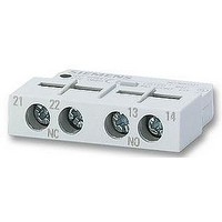
AUXILIARY SWITCH, LATERALLY FIT
Manufacturer
SIEMENS
Datasheet
1.3RV19011A.pdf
(56 pages)
Specifications of 3RV19011A
Approval Bodies
UL, CSA, VDE
Contact Configuration
1 N/C + 1 N/O
No. Of Poles
2
Terminal Type
Screw
Accessory Type
Lateral Auxilary Contact
For Use With
-000 A


■
Overview
(1) Connection for mounting onto contactors:
(2) Selector switch for manual/automatic RESET and RESET button:
(3) Switch position indicator and TEST function of the wiring:
(4) Solid-state test:
(5) Motor current setting:
(6) Trip class setting/internal ground-fault detection (only 3RB21):
(7) Connecting terminals (removable terminal block for auxiliary circuits):
Optimally adapted in electrical, mechanical and design terms to the
contactors and soft starters, these connecting pins can be used for
direct mounting of the overload relays. Stand-alone installation is
possible as an alternative (in some cases in conjunction with a stand-
alone installation module).
With the slide switch you can choose between manual and automatic
RESET. A device set to manual RESET can be reset locally by pressing
the RESET button. On the 3RB21 a solid-state remote RESET is
integrated.
Indicates a trip and enables the wiring test.
Enables a test of all important device components and functions.
Setting the device to the rated motor current is easy with the large
rotary knob.
Using the rotary switch you can set the required trip class and activate
the internal ground-fault detection dependent on the starting
conditions.
The generously sized terminals permit connection of two conductors
with different cross-sections for the main and auxiliary circuits. The
auxiliary circuit can be connected with screw-type terminals and
alternatively with spring-loaded terminals.
■
The 3RB20 and 3RB21 solid-state overload relays up to 630 A
with internal power supply have been designed for current-
dependent protection of loads with normal and heavy starting
(see LV 1 T, Function)
to overload, phase unbalance or phase failure. An overload,
phase unbalance or phase failure result in an increase of the
motor current beyond the set motor rated current. This current
rise is detected by the current transformers integrated into the
devices and evaluated by corresponding solid-state circuits
which then output a pulse to the auxiliary contacts. The auxiliary
contacts then switch off the load by means of a contactor. The
break time depends on the ratio between the tripping current
and set current I
tripping characteristic
In addition to current-dependent protection of loads against
excessive temperature rises due to overload, phase unbalance
and phase failure, the 3RB21 solid-state overload relays also
allow internal ground-fault detection (not possible in conjunction
with wye-delta assemblies). This provides protection of loads
against high-resistance short-circuits due to damage to the
insulation material, moisture, condensed water etc.
The "tripped" status is signaled by means of a switch position
indicator
manually or automatically after the recovery time has elapsed
(see LV 1 T,
The devices are manufactured in accordance with
environmental guidelines and contain environmentally friendly
and reusable materials. They comply with all important
worldwide standards and approvals.
Benefits
The most important features and benefits of the 3RB20/3RB21
solid-state overload relays are listed in the overview table
(see Overload Relays, General
(see LV 1 T,
3RB2 Solid-State Overload Relays
Function).
3RB20, 3RB21 for standard applications
e
and is stored in the form of a long-term stable
Function). Resetting takes place either
against excessive temperature rises due
(see LV 1 T, Characteristic
Overload Relays
Data).
Siemens LV 1 · 2006
Curves).
5/35
Related parts for 3RV19011A
Image
Part Number
Description
Manufacturer
Datasheet
Request
R

Part Number:
Description:
Intel 80C32 - Siemens SAB-C501, Nearest Equivalent Replacement
Manufacturer:
Siemens Semiconductor Group
Part Number:
Description:
IGBT MODULE
Manufacturer:
Siemens Semiconductor Group
Datasheet:
Part Number:
Description:
SIMOPAC Module (Power module Single switch N channel Enhancement mode)
Manufacturer:
Siemens Semiconductor Group
Datasheet:
Part Number:
Description:
(BSMxxx) TRANSISTOR
Manufacturer:
Siemens Semiconductor Group
Datasheet:
Part Number:
Description:
SIMOPAC Module (Power module Single switch N channel Enhancement mode)
Manufacturer:
Siemens Semiconductor Group
Datasheet:
Part Number:
Description:
main ratings
Manufacturer:
Siemens Semiconductor Group
Datasheet:
Part Number:
Description:
Manufacturer:
Siemens Semiconductor Group
Datasheet:
Part Number:
Description:
Manufacturer:
Siemens Semiconductor Group
Datasheet:
Part Number:
Description:
Manufacturer:
Siemens Semiconductor Group
Datasheet:
Part Number:
Description:
ICs for Consumer Electronics
Manufacturer:
Siemens Semiconductor Group
Datasheet:
Part Number:
Description:
Video and Sound IF with V & S SCART
Manufacturer:
Siemens Semiconductor Group
Datasheet:
Part Number:
Description:
Manufacturer:
Siemens Semiconductor Group
Datasheet:
Part Number:
Description:
Multistandard Sound IF
Manufacturer:
Siemens Semiconductor Group
Datasheet:
Part Number:
Description:
MULTISTANDARD AM FM SOUND IF IC
Manufacturer:
Siemens Semiconductor Group
Datasheet: