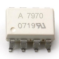
ACPL-7970-500E Avago Technologies US Inc., ACPL-7970-500E Datasheet - Page 7

ACPL-7970-500E
Manufacturer Part Number
ACPL-7970-500E
Description
IsolatedSigmaDelta Mod, TR+IEC+LF
Manufacturer
Avago Technologies US Inc.
Series
-r
Type
Sigma-Delta Modulatorr
Datasheet
1.ACPL-7970-000E.pdf
(18 pages)
Specifications of ACPL-7970-500E
Operating Supply Voltage
5.5 V
Supply Current
8 mA at 5 V
Operating Temperature Range
- 40 C to + 105 C
Mounting Style
SMD/SMT
Package / Case
DIP-8 Gull Wing
Input Voltage Range (max)
+ 200 mV
Voltage - Isolation
5000Vrms
Input Type
DC
Voltage - Supply
3 V ~ 5.5 V, 4.5 V ~ 5.5 V
Operating Temperature
-40°C ~ 105°C
Mounting Type
Surface Mount
Lead Free Status / Rohs Status
Details
Available stocks
Company
Part Number
Manufacturer
Quantity
Price
Table 7. Electrical Specifications
Unless otherwise noted, T
V
Notes:
1. All Typical values are at T
2. Beyond the full-scale input range the data output is either all zeroes or all ones.
3. Because of the switched-capacitor nature of the isolated modulator, time averaged values are shown.
4. V
7
Parameter
STATIC CHARACTERISTICS
Resolution
Integral Nonlinearity
Differential Nonlinearity
Offset Error
Offset Drift vs. Temperature
Offset Drift vs. V
Internal Reference Voltage
Reference Voltage Tolerance
V
V
ANALOG INPUTS
Full-Scale Differential Voltage
Input Range
Average Input Bias Current
Average Input Resistance
Input Capacitance
DYNAMIC CHARACTERISTICS
Signal-to-Noise Ratio
Signal-to-(Noise + Distortion)
Ratio
Effective Number of Bits
Isolation Transient Immunity
Common-Mode Rejection Ratio
DIGITAL OUTPUTS
Output High Voltage
Output Low Voltage
POWER SUPPLY
V
V
IN
REF
REF
DD1
DD2
– = 0 V (single-ended connection); tested with Sinc
REF
Drift vs. Temperature
Drift vs. V
Supply Current
Supply Current
Drift vs. V
DD1
DD1
DD1
can be expressed as –0.4%/V with reference to V
A
= 25° C, V
A
= -40° C to +105° C, V
DD1
Symbol
INL
DNL
V
TCV
V
G
TCG
FSR
I
R
C
SNR
SNDR
ENOB
CMR
CMRR
V
V
I
I
INA
DD1
DD2
IN
OS
REF
INA
OH
OL
E
= 5 V, V
OS
E
DD2
Min.
16
-15
-25
-0.9
-2
-1
-2
68
65
V
0.2
= 5 V.
DD2
–
DD1
Typ.
3
3
0.4
2.5
120
320
60
-1.3
320
-0.3
24
8
78
75
12
25
74
V
0.1
9
5.2
4.6
DD2
= 4.5 V to 5.5 V, V
[1]
3
–
filter, 256 decimation ratio.
REF
Max.
15
25
0.9
2
7
1
2
0.6
14
8
7
.
Units
Bits
LSB
LSB
LSB
mV
PV/°C
PV/V
mV
%
%
ppm/°C
mV/V
mV
PA
k:
pF
dB
dB
Bits
kV/Ps
dB
V
V
mA
mA
mA
DD2
= 3 V to 5.5 V, V
Test Conditions/Notes
Decimation filter output set to 16 bits
T
section
T
No missing codes, guaranteed by
design; see Definitions section
T
see Definitions section
V
T
see Definitions section
T
V
Note 4
V
V
Note 3
Across V
Across V
V
T
see Definitions section
T
see Definitions section
see Definitions section
V
I
I
V
V
V
OUT
OUT
A
A
A
A
A
A
A
DD1
IN
IN
DD1
IN
CM
IN
DD2
DD2
= -40° C to +85° C; see Definitions
= 85° C to 105° C
= -40° C to +105° C;
= 25° C, V
= -40° C to +105° C,
= -40° C to +105° C;
= -40° C to +105° C;
+ = -320 to +320 mV
+ = 400 mVpp, 1 kHz sine wave
+ = –320 mV to +320 mV
= V
= 1 kV; See Definitions section
= -200 PA
= +1.6 mA
= 5 V
= 5V, V
= 5 V supply
= 3.3 V supply
IN
IN
IN
+ – V
+ or V
+ or V
IN
DD2
IN
+ = -320 to +320 mV;
IN
–; Note 2
IN
IN
= 5V, V
+ = -200 mV to +200 mV, and
– to GND1; Note 3
– to GND1
IN
+ = 0 V;
Fig.
5
6
7
8
9
10
11
12


