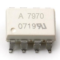
ACPL-7970-500E Avago Technologies US Inc., ACPL-7970-500E Datasheet - Page 8

ACPL-7970-500E
Manufacturer Part Number
ACPL-7970-500E
Description
IsolatedSigmaDelta Mod, TR+IEC+LF
Manufacturer
Avago Technologies US Inc.
Series
-r
Type
Sigma-Delta Modulatorr
Datasheet
1.ACPL-7970-000E.pdf
(18 pages)
Specifications of ACPL-7970-500E
Operating Supply Voltage
5.5 V
Supply Current
8 mA at 5 V
Operating Temperature Range
- 40 C to + 105 C
Mounting Style
SMD/SMT
Package / Case
DIP-8 Gull Wing
Input Voltage Range (max)
+ 200 mV
Voltage - Isolation
5000Vrms
Input Type
DC
Voltage - Supply
3 V ~ 5.5 V, 4.5 V ~ 5.5 V
Operating Temperature
-40°C ~ 105°C
Mounting Type
Surface Mount
Lead Free Status / Rohs Status
Details
Available stocks
Company
Part Number
Manufacturer
Quantity
Price
Table 8. Timing Specifications
Unless otherwise noted, T
Figure 4. Data timing.
Table 9. Package Characteristics
Notes:
1. In accordance with UL 1577, each optocoupler is proof tested by applying an insulation test voltage ≥ 6000 Vrms for 1 second (leakage detection
2. The Input-Output Momentary Withstand Voltage is a dielectric voltage rating that should not be interpreted as an input-output continuous
3. This is a two-terminal measurement: pins 1–4 are shorted together and pins 5–8 are shorted together.
8
Parameter
Modulator Clock Output Frequency
Data Access Time After MCLK Rising Edge
Data Hold Time After MCLK Rising Edge
MDAT
Parameter
Input-Output Momentary Withstand
Voltage
Input-Output Resistance
Input-Output Capacitance
MCLK
current limit, I
5-5 Insulation Characteristic Table.
voltage rating. For the continuous voltage rating, refer to the IEC/EN/DIN EN 60747-5-5 insulation characteristics table and your equipment level
safety specification.
I-O
≤ 5 PA). This test is performed before the 100% production test for partial discharge (method b) shown in IEC/EN/DIN EN 60747-
t
A
A
= -40° C to +105° C, V
Symbol
f
t
t
Symbol
V
R
C
MCLK
A
H
ISO
I-O
I-O
t
H
DD1
Min.
9
10
Min.
5000
10
10
= 4.5 V to 5.5 V, V
12
11
Typ.
10
Typ.
10
1.4
13
Max.
11
40
Max.
DD2
Units
MHz
ns
ns
Unit
Vrms
:
:
pF
= 3 V to 5.5 V.
Test Conditions/Notes
Clock duty cycle 40% to 60%
C
C
Test Condition
RH < 50%, t = 1 min; T
V
T
f = 1 MHz
A
L
L
I-O
= 100° C
= 15 pF
= 15 pF
= 500 V
DC
A
= 25° C
Fig.
13
4
4
Note
1, 2
3
3
3


