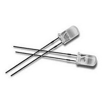
HLMP-HB55-FJ0DD Avago Technologies US Inc., HLMP-HB55-FJ0DD Datasheet - Page 10

HLMP-HB55-FJ0DD
Manufacturer Part Number
HLMP-HB55-FJ0DD
Description
LED Lamp
Manufacturer
Avago Technologies US Inc.
Datasheet
1.HLMP-HM55-MQ000.pdf
(12 pages)
Specifications of HLMP-HB55-FJ0DD
Color
Blue
Forward Voltage
3.8V
Input Current Max
30mA
Led Color
Blue
Led Gas Type
InGaN
Lead Pitch
2.54mm
Leaded Process Compatible
Yes
Lens Color
Blue
Lens Style
(H X Dia) 7 X 5.2 Mm
Lens Width
5.2mm
Millicandela Rating
210mcd
Current - Test
20mA
Wavelength - Dominant
470nm
Wavelength - Peak
467nm
Voltage - Forward (vf) Typ
3.2V
Lens Type
Clear, Blue Tinted
Lens Style/size
Oval, 5mm
Package / Case
Radial - 2 Lead
Height
7.00mm
Viewing Angle
100°, 40°
Mounting Type
Through Hole
Resistance Tolerance
470nm
Led Size
T-1 3/4
Illumination Color
Blue
Lens Color/style
Blue
Wavelength
470 nm
Mounting Style
Through Hole
Lead Free Status / RoHS Status
Lead free / RoHS Compliant
Luminous Flux @ Current - Test
-
Lead Free Status / Rohs Status
Details
10
Figure 8. Recommended wave soldering profile.
Avago Technologies LED Configuration
• If necessary, use fixture to hold the LED component
• At elevated temperature, the LED is more
• Special attention must be given to board fabrication,
Note: Electrical connection between bottom surface of LED die
and the lead frame material through conductive paste of solder.
in proper orientation with respect to the PCB
during soldering process.
susceptible to mechanical stress. Therefore, PCB
must be allowed to cool down to room temperature
prior to handling, which includes removal of jigs,
fixtures or pallet.
solder masking, surface platting and lead holes
size and component orientation to assure the
solderability.
250
200
150
100
50
30
0
10
CATHODE
FLUXING
20
PREHEAT
30
TURBULENT WAVE
40
TIME – SECONDS
50
60
70
LAMINAR WAVE
HOT AIR KNIFE
80
90
• Recommended PC board plated through hole sizes for
LED Component
Lead Size
0.457 x 0.457 mm
(0.018 x 0.018 inch)
0.508 x 0.508 mm
(0.020 x 0.020 inch)
• Over sizing of plated through hole can lead to
Note: Refer to application note AN1027 for more information on
soldering LED components.
LED component leads:
twisting or improper LED placement during auto
insertion. Under sizing plated through hole can
lead to mechanical stress on the epoxy lens during
clinching.
100
CONVEYOR SPEED = 1.83 M/MIN (6 FT/MIN)
PREHEAT SETTING = 150 C (100 C PCB)
SOLDER WAVE TEMPERATURE = 245 C 5 C
AIR KNIFE AIR TEMPERATURE = 390 C
AIR KNIFE DISTANCE = 1.91 mm (0.25 IN.)
AIR KNIFE ANGLE = 40
LEAD SOLDER: SN63; FLUX: RMA
LEAD FREE SOLDER: 96.5% Sn, 3.0% Ag, 0.5% Cu
NOTE: ALLOW FOR BOARDS TO BE
SUFFICIENTLY COOLED BEFORE
EXERTING MECHANICAL FORCE.
TOP SIDE
OF PC BOARD
BOTTOM SIDE
OF PC BOARD
Diagonal
0.646 mm
(0.025 inch)
0.718 mm
(0.028 inch)
Plated Through
Hole Diameter
0.976 to 1.078 mm
(0.038 to 0.042 inch)
1.049 to 1.150 mm
(0.041 to 0.045 inch)


