AD9858/PCBZ Analog Devices Inc, AD9858/PCBZ Datasheet - Page 21
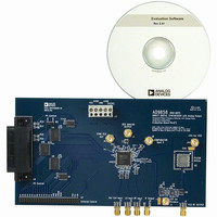
AD9858/PCBZ
Manufacturer Part Number
AD9858/PCBZ
Description
DIGITAL SYNTHESIZER
Manufacturer
Analog Devices Inc
Specifications of AD9858/PCBZ
Silicon Manufacturer
Analog Devices
Application Sub Type
Direct Digital Synthesizer
Kit Application Type
Clock & Timing
Silicon Core Number
AD9858
Kit Contents
Board
Design Resources
Low Jitter Sampling Clock Generator for High Performance ADCs Using AD9958/9858 and AD9515 (CN0109)
Main Purpose
Timing, Direct Digital Synthesis (DDS)
Utilized Ic / Part
AD9858/TL
Lead Free Status / RoHS Status
Lead free / RoHS Compliant
Embedded
-
Primary Attributes
-
Secondary Attributes
-
Lead Free Status / RoHS Status
Lead free / RoHS Compliant, Lead free / RoHS Compliant
Other names
AD9858/PCB
AD9858/PCB
AD9858/PCB


Serial Programming Mode
In serial programming mode, the I/O port uses a chip select pin
( CS ), a serial clock pin (SCLK), an I/O reset pin (IORESET),
and either one or two serial data pins (SDIO and/or SDO). The
number of serial data pins used depends on the configuration of
the I/O port, that is, whether it has been configured for 2-wire
or 3-wire serial operation as defined by the control function
register. In 2-wire mode, the SDIO pin operates as a bidirectional
serial data pin. In 3-wire mode, the SDIO pin operates as a
serial data input pin only, and the SDO pin acts as the serial
output. The maximum rate of SCLK is guaranteed only for write
operation.
The serial port is an SPI-compatible serial interface. Serial port
communication occurs in two phases. Phase 1 is an instruction
cycle consisting of an 8-bit word. The MSB of the instruction
byte flags the ensuing operation as a read or write operation.
The six LSBs define the serial address of the target register as
defined in the register map. The instruction byte format is given in
Table 5.
Table 5.
D7 (MSB)
1: Read
0: Write
Phase 2 of a serial port communication contains the data to be
routed to/from the addressed register. The number of bytes
transferred during Phase 2 depends on the length of the target
register. Serial operation requires that all bits associated with a
serial register address be transferred.
ADDR[5:0]
D[7:0]
RD
D6
X
A
D
D5
A5
1
1
SPECIFICATION
t
t
t
t
ADV
AHD
RDLOV
RDHOZ
t
D4
A4
RDHOZ
t
AHD
D3
A3
VALUE
15ns
5ns
15ns
10ns
D2
A2
t
t
RDLOV
ADV
D1
A1
DESCRIPTION
ADDRESS TO DATA VALID TIME (MAXIMUM)
ADDRESS HOLD TIME TO RD SIGNAL INACTIVE (MINIMUM)
RD LOW TO OUTPUT VALID (MAXIMUM)
RD HIGH TO DATA THREE-STATE (MAXIMUM)
Figure 36. I/O Port Read Cycle Timing (Parallel)
D0 (LSB)
A0
Rev. C | Page 21 of 32
A
D
2
2
Both phases of a serial port communication require the serial
data clock (SCLK) to be operating. When writing to the device,
serial bits are transferred on the rising edge of SCLK. When
reading from the device, serial output bits are transferred on the
falling edge of SCLK. The bit order for both phases of a serial
port communication is selectable via the control function register.
The CS pin serves as a chip select control line. When CS is in a
Logic 1 state, the SDO and SDIO pins are disabled (forced into a
high impedance state). When the CS pin is in a Logic 0 state,
the SDO and SDIO pins are active. This allows multiple devices
to reside on a single serial bus. If multiple devices are connected
to the same serial bus, then communication with an individual
device is accomplished by setting CS to a Logic 0 state on the
target device, but to a Logic 1 state on all other devices. In this
way, serial communication occurs only between the controller
and the target device.
When I/O synchronization is lost between the AD9858 and
the external controller, the IORESET pin provides a means
to reestablish synchronization without initializing the entire
device. Asserting the active high IORESET pin resets the serial
port state machine. This terminates the current I/O operation
and puts the device into a state in which the next eight SCLK
pulses are expected to be the instruction byte of the next I/O
transfer. Any information previously written to the memory
registers during the last valid communication cycle prior to loss
of synchronization remains intact.
A
3
D
3
AD9858
Related parts for AD9858/PCBZ
Image
Part Number
Description
Manufacturer
Datasheet
Request
R

Part Number:
Description:
BOARD EVAL TRANSLATION LOOP
Manufacturer:
Analog Devices Inc
Datasheet:
Part Number:
Description:
BOARD EVAL FOR AD9858/FD
Manufacturer:
Analog Devices Inc
Datasheet:
Part Number:
Description:
BOARD EVAL FOR AD9858/TL
Manufacturer:
Analog Devices Inc
Datasheet:

Part Number:
Description:
±1.7g Dual-Axis IMEMS Accelerometer Evaluation Board
Manufacturer:
Analog Devices Inc
Datasheet:
Part Number:
Description:
Inertial Sensor Evaluation System
Manufacturer:
Analog Devices Inc
Datasheet:
Part Number:
Description:
Manufacturer:
Analog Devices Inc
Datasheet:
Part Number:
Description:
Manufacturer:
Analog Devices Inc
Datasheet:
Part Number:
Description:
Manufacturer:
Analog Devices Inc
Datasheet:
Part Number:
Description:
Manufacturer:
Analog Devices Inc
Datasheet:
Part Number:
Description:
Manufacturer:
Analog Devices Inc
Datasheet:
Part Number:
Description:
Manufacturer:
Analog Devices Inc
Datasheet:
Part Number:
Description:
Manufacturer:
Analog Devices Inc
Datasheet:
Part Number:
Description:
Manufacturer:
Analog Devices Inc
Datasheet: