AD9858/PCBZ Analog Devices Inc, AD9858/PCBZ Datasheet - Page 23
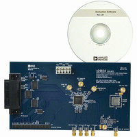
AD9858/PCBZ
Manufacturer Part Number
AD9858/PCBZ
Description
DIGITAL SYNTHESIZER
Manufacturer
Analog Devices Inc
Specifications of AD9858/PCBZ
Silicon Manufacturer
Analog Devices
Application Sub Type
Direct Digital Synthesizer
Kit Application Type
Clock & Timing
Silicon Core Number
AD9858
Kit Contents
Board
Design Resources
Low Jitter Sampling Clock Generator for High Performance ADCs Using AD9958/9858 and AD9515 (CN0109)
Main Purpose
Timing, Direct Digital Synthesis (DDS)
Utilized Ic / Part
AD9858/TL
Lead Free Status / RoHS Status
Lead free / RoHS Compliant
Embedded
-
Primary Attributes
-
Secondary Attributes
-
Lead Free Status / RoHS Status
Lead free / RoHS Compliant, Lead free / RoHS Compliant
Other names
AD9858/PCB
AD9858/PCB
AD9858/PCB


Register
Name
Phase
Offset
Word 2
(POW2)
Frequency
Tuning
Word 3
(FTW3)
Phase
Offset
Word 3
(POW3)
Reserved
REGISTER BIT DESCRIPTIONS
Control Function Register (CFR)
The CFR comprises four bytes. CFR is used to control the
various functions, features, and modes of the AD9858. The
functionality of each bit follows. Note that the register bits are
identified according to their serial register bit locations beginning
with the most significant bit.
CFR[31:30]: Frequency Detect Mode Charge Pump Current
These bits are used to set the scale factor for the frequency
detect mode charge pump output current (see Table 7). The
charge pump delivers the scaled output current when the
control logic forces the charge pump into its frequency detect
operating mode. The charge pump’s baseline output current
(I
given by
The recommended nominal value of the CPISET resistor is
2.4 kΩ, which yields a baseline current of 500 μA.
Table 7.
CFR[31:30]
00
01
10
11
CFR[29:27]: Final Closed-Loop Mode Charge Pump
Current
These bits are used to set the scale factor for the final closed-
loop mode charge pump output current (see Table 8). The
charge pump delivers the scaled output current when the control
logic forces the charge pump into its final closed-loop mode.
CP0
) is determined by the external CPISET resistor and is
I
CP0
= 1.24/ CPISET
Ser
0x08
0x09
0x0A
0x0B
Frequency Detect Mode
Charge Pump Scale Value
0
2
3
4
Address
Par
0x1A
0x1B
0x1C
0x1D
0x1E
0x1F
0x20
0x21
0x22
0x23
(MSB)
Bit 7
Not used
Not used
Bit 6
Notes
I
I
I
I
OUT
OUT
OUT
OUT
= 0 (default)
= 20 × I
= 40 × I
= 60 × I
Bit 5
Reserved, do not write, leave at 0xFF
Reserved, do not write, leave at 0xFF
Frequency Tuning Word 3[23:16]
Frequency Tuning Word 3[31:24]
CP0
CP0
CP0
Frequency Tuning Word 3[15:8]
Frequency Tuning Word 3[7:0]
Rev. C | Page 23 of 32
Phase Offset Word 2[7:0]
Phase Offset Word 3[7:0]
Bit 4
Phase Offset Word 2[13:8]
Phase Offset Word 3[13:8]
Table 8.
CFR[29:27]
0xx
100
101
110
111
CFR[26:24]: Wide Closed-Loop Mode Charge Pump
Current
These bits are used to set the scale factor for the wide closed-
loop charge pump output current (see Table 9). The charge
pump delivers the scaled output current when the control logic
forces the charge pump into its wide closed-loop operating mode.
Table 9.
CFR[26:24]
000
001
010
011
100
101
110
111
CFR[23]: Auto Clear Frequency Accumulator Bit
When CFR[23] = 0 (default), a new delta frequency word is
applied to the input of the accumulator and added to the
currently stored value.
When CFR[23] = 1, this bit automatically synchronously clears
(loads zeros into) the frequency accumulator for one cycle upon
reception of the FUD sequence indicator.
Bit 3
Bit 2
Wide Closed-Loop Mode
Charge Pump Scale Value
0
2
4
6
8
10
12
14
Final Closed-Loop Mode
Charge Pump Scale Value
0
1
2
3
4
Bit 1
(LSB)
Bit 0
Default
Value
0xFE
0xFF
Notes
I
I
I
I
I
Notes
I
I
I
I
I
I
I
I
OUT
OUT
OUT
OUT
OUT
OUT
OUT
OUT
OUT
OUT
OUT
OUT
OUT
= 0 (default)
= I
= 2 × I
= 3 × I
= 4 × I
= 0 (default)
= 2 × I
= 4 × I
= 6 × I
= 8 × I
= 10 × I
= 12 × I
= 14 × I
AD9858
CP0
CP0
CP0
CP0
CP0
CP0
CP0
CP0
Profile
2
2
3
3
3
3
3
3
N/A
N/A
CP0
CP0
CP0
Related parts for AD9858/PCBZ
Image
Part Number
Description
Manufacturer
Datasheet
Request
R

Part Number:
Description:
BOARD EVAL TRANSLATION LOOP
Manufacturer:
Analog Devices Inc
Datasheet:
Part Number:
Description:
BOARD EVAL FOR AD9858/FD
Manufacturer:
Analog Devices Inc
Datasheet:
Part Number:
Description:
BOARD EVAL FOR AD9858/TL
Manufacturer:
Analog Devices Inc
Datasheet:

Part Number:
Description:
±1.7g Dual-Axis IMEMS Accelerometer Evaluation Board
Manufacturer:
Analog Devices Inc
Datasheet:
Part Number:
Description:
Inertial Sensor Evaluation System
Manufacturer:
Analog Devices Inc
Datasheet:
Part Number:
Description:
Manufacturer:
Analog Devices Inc
Datasheet:
Part Number:
Description:
Manufacturer:
Analog Devices Inc
Datasheet:
Part Number:
Description:
Manufacturer:
Analog Devices Inc
Datasheet:
Part Number:
Description:
Manufacturer:
Analog Devices Inc
Datasheet:
Part Number:
Description:
Manufacturer:
Analog Devices Inc
Datasheet:
Part Number:
Description:
Manufacturer:
Analog Devices Inc
Datasheet:
Part Number:
Description:
Manufacturer:
Analog Devices Inc
Datasheet:
Part Number:
Description:
Manufacturer:
Analog Devices Inc
Datasheet: