DK-START-4CGX15N/P Altera, DK-START-4CGX15N/P Datasheet - Page 21
DK-START-4CGX15N/P
Manufacturer Part Number
DK-START-4CGX15N/P
Description
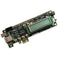
Cyclone IV Tranceiver Development Kit
Manufacturer
Altera
Datasheet
1.DK-START-4CGX15N.pdf
(40 pages)
Specifications of DK-START-4CGX15N/P
Silicon Manufacturer
Altera
Features
System Controller Enabling Passive Serial, Flash/SRAM Memory Devices, PCI Express Edge Connector
Kit Contents
Board, Cables, PSU, CD
Core Architecture
FPGA
Core Sub-architecture
Cyclone
Silicon Core Number
EP4C
Silicon Family Name
Cyclone IV GX
Rohs Compliant
Yes
Lead Free Status / RoHS Status
Lead free / RoHS Compliant


Chapter 2: Board Components
Configuration, Status, and Setup Elements
Status Elements
Table 2–9. Board-Specific LEDs
Table 2–10. Board-Specific LEDs Component References and Manufacturing Information
Setup Elements
© March 2010 Altera Corporation
Board Reference
Board Reference
D2-D4, D13-D18
D3, D4
D12
D13
D14
D15
D16
D17
D18
D1
D2
D12
D1
MAX_ERROR
CONF_DONE_LED
PROGRAM
(PGM_LED1,PGM_LED0)
Power
USB_LED
ENET_LEDR_TX
ENET_LEDR_RX
ENET_LEDR_LINK1000
ENET_LEDR_LINK100
ENET_LEDR_LINK10
The starter board includes status LEDs. This section describes the status elements.
Table 2–9
Table 2–10
information.
The starter board includes several different kinds of setup elements. This section
describes the following setup elements:
■
■
■
Board settings DIP switch
Configuration settings DIP switch
Configuration push-button switches
LED Name
Description
Green LEDs
Blue LED
Red LED
lists the LED board references, names, and functional descriptions.
lists the board-specific LEDs component references and manufacturing
Manufacturer
Lumex, Inc.
Lumex, Inc.
Lumex, Inc.
Green LED. Illuminates when the FPGA is successfully configured. Driven
Blue LED. Illuminates when 9-V – 16-V power is active.
Green LED. Illuminates when the embedded USB-Blaster is in use to
Green LED. Illuminates to indicate Ethernet PHY transmit activity. Driven
Green LED. Illuminates to indicate Ethernet PHY receive activity. Driven
Green LED. Illuminates to indicate Ethernet linked at 1000 Mbps
Green LED. Illuminates to indicate Ethernet linked at 100 Mbps
Green LED. Illuminates to indicate Ethernet linked at 10 Mbps connection
Red LED. Illuminates when the MAX II CPLD EPM2210 System Controller
fails to configure the FPGA. Driven by the MAX II CPLD EPM2210 System
Controller.
by the MAX II CPLD EPM2210 System Controller.
Green LEDs. Illuminates to show the LED sequence that determines
which flash memory image loads to the FPGA when PGM select
push-button switch is pressed. Driven by the MAX II CPLD EPM2210
System Controller.
program the FPGA. Driven by the MAX II CPLD EPM2210 System
Controller and MAX IIZ.
by the Marvell 88E1111 PHY.
by the Marvell 88E1111 PHY.
connection speed. Driven by the Marvell 88E1111 PHY.
connection speed. Driven by the Marvell 88E1111 PHY.
speed. Driven by the Marvell 88E1111 PHY.
Manufacturer Part Number
SML-LX1206USBC-TR
SML-LXT0805IW-TR
SML-LX1206GC-TR
Cyclone IV GX Transceiver Starter Board Reference Manual
Description
Manufacturer Website
www.lumex.com
www.lumex.com
www.lumex.com
2–13
Related parts for DK-START-4CGX15N/P
Image
Part Number
Description
Manufacturer
Datasheet
Request
R

Part Number:
Description:
KIT STARTER CYCLONE III EP3C25
Manufacturer:
Altera
Datasheet:

Part Number:
Description:
KIT STARTER CYCLONE IV GX
Manufacturer:
Altera
Datasheet:

Part Number:
Description:
Programmable Logic IC Development Tools FPGA Development Kit For 5AGXFB3H4F35C5N
Manufacturer:
Altera Corporation
Datasheet:
Part Number:
Description:
Programmable Logic IC Development Tools FPGA Starter Kit For 5AGXFB3H4F
Manufacturer:
Altera Corporation
Datasheet:

Part Number:
Description:
KIT, DEV, PCI EXPRESS, ECP2M
Manufacturer:
LATTICE SEMICONDUCTOR

Part Number:
Description:
CYCLONE II STARTER KIT EP2C20N
Manufacturer:
Altera
Datasheet:

Part Number:
Description:
CPLD, EP610 Family, ECMOS Process, 300 Gates, 16 Macro Cells, 16 Reg., 16 User I/Os, 5V Supply, 35 Speed Grade, 24DIP
Manufacturer:
Altera Corporation
Datasheet:
Part Number:
Description:
CPLD, EP610 Family, ECMOS Process, 300 Gates, 16 Macro Cells, 16 Reg., 16 User I/Os, 5V Supply, 15 Speed Grade, 24DIP
Manufacturer:
Altera Corporation
Datasheet:
Part Number:
Description:
Manufacturer:
Altera Corporation
Datasheet:
Part Number:
Description:
CPLD, EP610 Family, ECMOS Process, 300 Gates, 16 Macro Cells, 16 Reg., 16 User I/Os, 5V Supply, 30 Speed Grade, 24DIP
Manufacturer:
Altera Corporation
Datasheet:
Part Number:
Description:
High-performance, low-power erasable programmable logic devices with 8 macrocells, 10ns
Manufacturer:
Altera Corporation
Datasheet:
Part Number:
Description:
High-performance, low-power erasable programmable logic devices with 8 macrocells, 7ns
Manufacturer:
Altera Corporation
Datasheet:
Part Number:
Description:
Classic EPLD
Manufacturer:
Altera Corporation
Datasheet: