DK-START-4CGX15N/P Altera, DK-START-4CGX15N/P Datasheet - Page 30
DK-START-4CGX15N/P
Manufacturer Part Number
DK-START-4CGX15N/P
Description
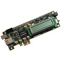
Cyclone IV Tranceiver Development Kit
Manufacturer
Altera
Datasheet
1.DK-START-4CGX15N.pdf
(40 pages)
Specifications of DK-START-4CGX15N/P
Silicon Manufacturer
Altera
Features
System Controller Enabling Passive Serial, Flash/SRAM Memory Devices, PCI Express Edge Connector
Kit Contents
Board, Cables, PSU, CD
Core Architecture
FPGA
Core Sub-architecture
Cyclone
Silicon Core Number
EP4C
Silicon Family Name
Cyclone IV GX
Rohs Compliant
Yes
Lead Free Status / RoHS Status
Lead free / RoHS Compliant


2–22
Transceiver SMA Connectors (Optional)
Table 2–27. Multiplexer Locations for the Ethernet PHY Connection and Transceiver SMAs Connectors
Memory
SSRAM
Cyclone IV GX Transceiver Starter Board Reference Manual
R53, R52, R54, R51
R53, R52, R54, R51
C59, C58, C60, C57
C59, C58, C60, C57
Board Reference
Board references J9 and J8 are two optional input SMAs to the high-speed positive
and negative differential receiver channel while J11 and J10 are two optional output
SMAs from the high-speed positive and negative differential transmitter channel. By
default, the GXB_RX1 channel of the FPGA is connected to the Ethernet PHY through
capacitor multiplexer C59 and C58, while the GXB_TX1 channel is connected to the
Ethernet PHY through resistor multiplexer R53 and R52. You need to perform a solder
modification on the board if you intend to use the optional transceiver SMA
connectors. You can use these SMAs to connect to external circuit boards or
daughtercards for transceiver applications.
Table 2–27
default Ethernet PHY connection or the optional transceiver SMA connectors. The
capacitors multiplexer are 0.1-μF capacitors and the multiplexer resistors are 0-Ω
resistors.
This section describes the board's memory interface support and also their signal
names, types, and connectivity relative to the Cyclone IV GX device. The board has
the following memory interfaces:
■
■
The SSRAM device consists of a single standard synchronous SRAM, providing
18-Mb of memory with a 16-bit data bus. This device is part of the shared FSML bus
which connects to the flash memory, SRAM, and MAX II CPLD EPM2210 System
Controller.
Table 2–28
names and types are relative to the Cyclone IV GX device in terms of I/O setting and
direction.
SSRAM
Flash
Ethernet PHY RX enable
Ethernet PHY TX enable
Transceiver SMA RX enable
Transceiver SMA TX enable
shows the capacitor and resistor multiplexer locations to enable either the
lists the SSRAM pin assignments, signal names, and functions. The signal
Description
■
■
■
■
■
■
■
■
Populate C59 and C58
Unpopulate C60 and C57 (default)
Populate R53 and R52
Unpopulate R54 and R51 (default)
Populate C60 and C57
Unpopulate C59 and C58
Populate R54 and R51
Unpopulate R53 and R52
Multiplexer Location
© March 2010 Altera Corporation
Chapter 2: Board Components
Memory
Related parts for DK-START-4CGX15N/P
Image
Part Number
Description
Manufacturer
Datasheet
Request
R

Part Number:
Description:
KIT STARTER CYCLONE III EP3C25
Manufacturer:
Altera
Datasheet:

Part Number:
Description:
KIT STARTER CYCLONE IV GX
Manufacturer:
Altera
Datasheet:

Part Number:
Description:
Programmable Logic IC Development Tools FPGA Development Kit For 5AGXFB3H4F35C5N
Manufacturer:
Altera Corporation
Datasheet:
Part Number:
Description:
Programmable Logic IC Development Tools FPGA Starter Kit For 5AGXFB3H4F
Manufacturer:
Altera Corporation
Datasheet:

Part Number:
Description:
KIT, DEV, PCI EXPRESS, ECP2M
Manufacturer:
LATTICE SEMICONDUCTOR

Part Number:
Description:
CYCLONE II STARTER KIT EP2C20N
Manufacturer:
Altera
Datasheet:

Part Number:
Description:
CPLD, EP610 Family, ECMOS Process, 300 Gates, 16 Macro Cells, 16 Reg., 16 User I/Os, 5V Supply, 35 Speed Grade, 24DIP
Manufacturer:
Altera Corporation
Datasheet:
Part Number:
Description:
CPLD, EP610 Family, ECMOS Process, 300 Gates, 16 Macro Cells, 16 Reg., 16 User I/Os, 5V Supply, 15 Speed Grade, 24DIP
Manufacturer:
Altera Corporation
Datasheet:
Part Number:
Description:
Manufacturer:
Altera Corporation
Datasheet:
Part Number:
Description:
CPLD, EP610 Family, ECMOS Process, 300 Gates, 16 Macro Cells, 16 Reg., 16 User I/Os, 5V Supply, 30 Speed Grade, 24DIP
Manufacturer:
Altera Corporation
Datasheet:
Part Number:
Description:
High-performance, low-power erasable programmable logic devices with 8 macrocells, 10ns
Manufacturer:
Altera Corporation
Datasheet:
Part Number:
Description:
High-performance, low-power erasable programmable logic devices with 8 macrocells, 7ns
Manufacturer:
Altera Corporation
Datasheet:
Part Number:
Description:
Classic EPLD
Manufacturer:
Altera Corporation
Datasheet: