CMD-711EX AXIOM, CMD-711EX Datasheet - Page 10
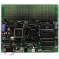
CMD-711EX
Manufacturer Part Number
CMD-711EX
Description
Microprocessor Development Tool
Manufacturer
AXIOM
Datasheet
1.CMD-711EX.pdf
(15 pages)
Specifications of CMD-711EX
Silicon Manufacturer
Freescale
Kit Contents
Board
Silicon Family Name
68HC11E
Silicon Core Number
MC68HC11E9FN, MC68HC11E20FN
Development Tool Type
Hardware - Eval/Demo Board
Lead Free Status / RoHS Status
Contains lead / RoHS non-compliant


JUMPERS AND SWITCHES
EA/E Jumpers
This block of 5 jumpers allow configuring for the EX series (default) or EA type HC11 micro-controllers. You
can use these jumpers to reconfigure the EX pin connections of the 52-pin PLC device to support the EA series
parts. See the schematic for more information.
MODE SWITCH
Normally the MODE SWITCH should be set to ALL OFF which is normal running mode. The individual switch
settings are as follows:
RESET SWITCH
Reset is provided by an 8054 low voltage detector when Vdd falls below approximately 4.4 volts. Manual reset
is provided by the RESET push button located next to the COM1 port on the board.
BUS_EN
JP1
JP2
JP3
JP4
JP5
JP6
JP7
JP9
1
2
3
4
5
6
7
8
ON enables A13 to U3. Normally this should never be removed, except when using an 8K
device in U3.
ON enables A14 to pin 1 of U4 (RAM or EEPROM)
ON enables A14 to pin 27 of U4 (EPROM only). Not installed if JP4 is ON.
ON write enables U4 pin 27 (RAM or EEPROM). Not installed if JP3 is ON.
ON enables A13 to pin 26 of U4. Removed for installing an 8k device.
ON enables A14 to pin 1 of U5 (EEPROM)
ON enables A14 to pin 27 of U5 (EPROM)
ON synchronizes the CS0 - CS7 chip selects with the E CLOCK, which allows for simple
latches (374 or 245 for example) to be used with CS0 - CS7.
OFF synchronizes the chip selects with valid address decoding. Control signals OE & WE
should be used with peripherals connected to the chip selects in this mode.
ON disables the HC24 Port Replacement unit (U2) and all external memory devices and
bus operation. This is "true single chip" mode with Mode Switch position 1 ON.
ON configures the HC11 MODA to Ground or 0 volts. See table.
ON configures the HC11 MODB to Ground or 0 volts. See table.
ON Write Enables External Program memory (U5).
ON Enables 20K program space in the external memory map.
ON Disables the Peripheral Chip Selects
ON Enables monitor TRACE operation using PA3 / XIRQ.
ON Enables Internal Memory Programming using Vpp / XIRQ.
ON Turns on Vpp Programming Voltage
10
on
on
off
1
HC11 MODE Table
on
off
off
2
Normal Expanded
True Single Chip
Bootstrap / utility
Mode
Related parts for CMD-711EX
Image
Part Number
Description
Manufacturer
Datasheet
Request
R

Part Number:
Description:
Single Board Computer
Manufacturer:
AXIOM
Datasheet:


Part Number:
Description:
General Power Transformer <SMD Type: CMD Series>
Manufacturer:
Sumida Corporation
Part Number:
Description:
Power Inductors <SMD Type: CMD Series>
Manufacturer:
Sumida Corporation
Part Number:
Description:
General Power Transformer <SMD Type: CMD Series>
Manufacturer:
Sumida Corporation

Part Number:
Description:
Linear Regulators - Standard VDDQ/VTT Regulator P2 Fused
Manufacturer:
CMD / ON Semiconductor
Part Number:
Description:
Switching Converters, Regulators & Controllers Charge Pump LDO
Manufacturer:
CMD / ON Semiconductor