CMD-711EX AXIOM, CMD-711EX Datasheet - Page 13
CMD-711EX
Manufacturer Part Number
CMD-711EX
Description
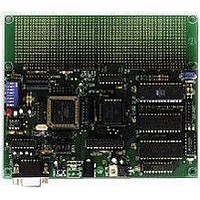
Microprocessor Development Tool
Manufacturer
AXIOM
Datasheet
1.CMD-711EX.pdf
(15 pages)
Specifications of CMD-711EX
Silicon Manufacturer
Freescale
Kit Contents
Board
Silicon Family Name
68HC11E
Silicon Core Number
MC68HC11E9FN, MC68HC11E20FN
Development Tool Type
Hardware - Eval/Demo Board
Lead Free Status / RoHS Status
Contains lead / RoHS non-compliant


I/O POINTS
The following connector points on the board do not have connectors attached but are provided for easy access.
COM1 Points
These points 9 8 7 6 4 1 located next to the DB-9 serial port connector COM1, can be used to connect the
COM1 lines that are unused by the DB-9 connector to provide hardware handshaking back to the PC or other
connected device. The board is shipped with all points (except 9) connected by cut-away traces on the bottom
of the board.
Q2, Q4 and Q6 Points
These points, located near the LCD port, are provided for decoding peripheral control signals. They are all
Active High, and can be used to connect larger LCD panels or simple 373 style latches for example.
MISCELLANEOUS
Power Jack
The required 9V operating power can be supplied by inserting the "barrel" type connector of the supplied wall plug
adapter into the power connector on the board, located near the serial port.
External power and ground points, beside the power connector, can also be used as alternate input power and ground
to the board OR to draw external power and ground from the board for external devices.
LED Indicators
Monitor Trace Switch
Mode Switch 6 is used by the included Buffalo Monitor for Trace and Single Step functions. These functions can be
enabled by setting Mode Switch 6 to the ON position. This will connect the PA3 Output Compare 5 pin to the XIRQ
line for nonmaskable interrupt service to implement software Trace and Single Step.
Exercise caution when using this mode that no other connections are made to the XIRQ or PA5 I/O pins of the
68HC11.
A/D Reference
The VRH and VRL lines from the HC11 are connected to +5v through R3 and Ground through R2. These two
surface mount resistors are on the bottom (solder) side of the circuit board. The resistors are identified on the silk
screen by their reference designators and the dashed line box that surrounds them. The appropriate resistor(s) need
to be removed in order to apply an external reference to the VRH and/or VRL inputs.
GREEN
RED
Point
Q2
Q4
Q6
Power ON
VPP Programming Voltage ON
Address
B5FC
B5F4
B5F8
13
Related parts for CMD-711EX
Image
Part Number
Description
Manufacturer
Datasheet
Request
R

Part Number:
Description:
Single Board Computer
Manufacturer:
AXIOM
Datasheet:


Part Number:
Description:
General Power Transformer <SMD Type: CMD Series>
Manufacturer:
Sumida Corporation
Part Number:
Description:
Power Inductors <SMD Type: CMD Series>
Manufacturer:
Sumida Corporation
Part Number:
Description:
General Power Transformer <SMD Type: CMD Series>
Manufacturer:
Sumida Corporation

Part Number:
Description:
Linear Regulators - Standard VDDQ/VTT Regulator P2 Fused
Manufacturer:
CMD / ON Semiconductor
Part Number:
Description:
Switching Converters, Regulators & Controllers Charge Pump LDO
Manufacturer:
CMD / ON Semiconductor