10-140 Cinch Connectors, 10-140 Datasheet - Page 249
10-140
Manufacturer Part Number
10-140
Description
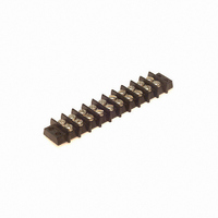
CONN BARRIER BLOCK .375" 10 POS
Manufacturer
Cinch Connectors
Series
140r
Type
Wire to Boardr
Specifications of 10-140
Pitch
0.375" (9.53mm)
Color
Black
Terminal Block Type
Barrier Block
Number Of Circuits
10
Number Of Positions
20
Number Of Rows
2
Current
15A
Voltage
250V
Wire Gauge
16 AWG
Mounting Type
Chassis Mount or Panel Mount
Top Termination
Screws
Bottom Termination
Closed
Barrier Type
2 Wall (Dual)
Features
Flange
Operating Temperature
-55°F ~ 300°F
Material - Insulation
Phenol Formaldehyde (Phenolic)
Material Flammability Rating
UL94 V-1
Product
Barrier Terminal Blocks
Number Of Positions / Contacts
10
Current Rating
15 A
Voltage Rating
250 V
Mounting Style
Through Hole
Termination Style
Screw
Flammability Rating
UL 94 V-0
Length
104.78 mm
Wire Gauge Max (awg)
16
Current, Rating
15 A (Max.)
Material, Block
Phenolic
Material, Screw
Steel
Plating, Screw
Nickel over Copper Flash
Screw Size
5-40 x 3⁄16
Temperature Range
-55 to +300 °F
Lead Free Status / RoHS Status
Lead free / RoHS Compliant
Lead Free Status / RoHS Status
Lead free / RoHS Compliant, Lead free / RoHS Compliant
Other names
10-140-P
10140-P
CBB110
10140-P
CBB110


180° (Top-Entry) Cable
Top-Entry products include a connector, hood (or overmold can), and associated hardware.
They are typically used at the end of a cable, where it is subject to physical strain and protection of the termination
area is required.
Dimensions
Size
14
24
36
50
.085 in. (2.16mm)
Density
Miniature Ribbon
•
•
•
•
•
Plug
Socket
Includes all hardware required to attach hood to connector.
Bail latching sockets have latch hardware integral to the connector body, making cable assembly more efficient.
Bail latching plugs include notches that lock with industry-standard bail-latch sockets.
Select configurations are available as overmold kits, which lower assembly costs by eliminating premolding and foil
soldering. Kits include connector and overmold cans. Crimp ferrules, which ground cable shields and provide strain relief,
must be ordered separately.
Ordering information for crimp ferrules is at end of end-entry product section. See page 6-22.
1.417
1.842
2.352
2.947
in
A
35.99
46.79
59.74
74.85
mm
C
1.750
2.175
2.685
3.270
in
B
H
44.45
55.25
68.20
83.06
mm
.306
.473
.639
.766
in
C
11.10
16.23
19.46
mm
7.77
IDC
Metal Shell
1.495
1.920
2.431
3.025
in
D
6-19
37.97
48.77
61.75
76.84
mm
1.83
2.43
-
-
in
E
mm
46.48
61.72
-
-
Deg.
F
37°
27°
Call Toll Free: 1 (800) 323-9612
-
-
.422
.473
.473
.473
in
G
10.72
12.01
12.01
12.01
mm
.843
.825
.905
.995
in
H
21.41
20.96
22.99
25.27
mm
.52
.60
in
-
-
M
13.21
15.24
mm
-
-
6
Related parts for 10-140
Image
Part Number
Description
Manufacturer
Datasheet
Request
R

Part Number:
Description:
CONN BARRIER BLOCK .438" 10 POS
Manufacturer:
Cinch Connectors
Datasheet:

Part Number:
Description:
CONN BARRIER BLOCK .563" 10 POS
Manufacturer:
Cinch Connectors
Datasheet:

Part Number:
Description:
CONN BARRIER BLOCK .375" 10 POS
Manufacturer:
Cinch Connectors
Datasheet:

Part Number:
Description:
TERMINAL BLOCK JUMPER TYPE F
Manufacturer:
Cinch Connectors
Datasheet:

Part Number:
Description:
D-Subminiature Connectors MCHNED PIN 20-24AWG
Manufacturer:
Cinch Connectors
Datasheet:
Part Number:
Description:
Terminal Block,4 Contacts,0.44 Pitch
Manufacturer:
Cinch Connectors
Datasheet:

Part Number:
Description:
Terminal Block,8 Contacts,0.375 Pitch
Manufacturer:
Cinch Connectors
Datasheet: