10-140 Cinch Connectors, 10-140 Datasheet - Page 95
10-140
Manufacturer Part Number
10-140
Description
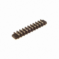
CONN BARRIER BLOCK .375" 10 POS
Manufacturer
Cinch Connectors
Series
140r
Type
Wire to Boardr
Specifications of 10-140
Pitch
0.375" (9.53mm)
Color
Black
Terminal Block Type
Barrier Block
Number Of Circuits
10
Number Of Positions
20
Number Of Rows
2
Current
15A
Voltage
250V
Wire Gauge
16 AWG
Mounting Type
Chassis Mount or Panel Mount
Top Termination
Screws
Bottom Termination
Closed
Barrier Type
2 Wall (Dual)
Features
Flange
Operating Temperature
-55°F ~ 300°F
Material - Insulation
Phenol Formaldehyde (Phenolic)
Material Flammability Rating
UL94 V-1
Product
Barrier Terminal Blocks
Number Of Positions / Contacts
10
Current Rating
15 A
Voltage Rating
250 V
Mounting Style
Through Hole
Termination Style
Screw
Flammability Rating
UL 94 V-0
Length
104.78 mm
Wire Gauge Max (awg)
16
Current, Rating
15 A (Max.)
Material, Block
Phenolic
Material, Screw
Steel
Plating, Screw
Nickel over Copper Flash
Screw Size
5-40 x 3⁄16
Temperature Range
-55 to +300 °F
Lead Free Status / RoHS Status
Lead free / RoHS Compliant
Lead Free Status / RoHS Status
Lead free / RoHS Compliant, Lead free / RoHS Compliant
Other names
10-140-P
10140-P
CBB110
10140-P
CBB110


Bayonet Coupling
CN1021XXXXXXXX
BACC63CC
Dimensions
Shell
Ordering Information
Notes:
1
2
• For mounting hole dimensions, see page 3-20.
* Th’d: UNS-2A
** Size 28 = 1.457 (37.008)
* Former order code - 100 designated rhodium plated contacts
CN1021 Series (C48 Family)
Vibration-Resistant Receptacle
Size
10
12
14
16
18
20
22
24
28
For Boeing Specification, see page 3-14.
For modifications, classes, etc. not listed, consult factory.
8
1.031
1.125
1.250
1.343
1.437
1.562
1.703
2.000
+.0045 (.114)
.812
.937
in
1
A
20.625
23.800
26.187
28.575
31.750
34.112
36.500
39.675
43.256
50.800
mm
Series Designation
CN1021
Series Modification
A - Square-Flange Mount
C - Square-Flange with Clinch Nuts
Shell Size
8, 10, 12, 14, 16, 18, 20, 22, 24, 26, 28
Environmental Class
A - Anodized Aluminum
G - Cadmium/Nickel-Plated Aluminum
2
1.062
1.156
1.250
1.375
1.562
.594
.719
.812
.906
.969
+.005 (.127)
in
B
15.088
18.263
20.625
23.012
24.613
26.975
29.362
31.750
34.925
39.675
mm
1.062 23.749
1.187 30.150
1.312 33.325
1.437 36.500
1.562 39.675
1.810 45.976
.561 14.250
.696 14.250
.875 17.679
.935 22.225
in
CN1021 A 10 G 05 P N - 000
Max.
C
mm
3-18
1.106
1.235
1.485
.328
.371
.547
.609
.758
.865
.986
in
Max. Dia.
D
13.894
15.469
19.253
21.971
25.044
28.092
31.369
37.719
8.331
9.423
mm
Call Toll Free: 1 (800) 323-9612
UNEF-2A
1.000-20
1.0625-18
1.1875-18
1.3125-18
1.4375-18
1.750-18*
Thread
.500-20
.625-24
.750-20
.875-20
L
Order Code (Deviations)
000 - Less Contacts
100 - * See below
200 - With Gold-Plated Contacts
Alternate Shell Position
N, 6, 7, 8, 9, 10
Per table on page 3-4.
Contact Style
P - Pin
S - Socket
Insert Arrangements
(See page 3-4)
(35.738)
1.407**
Max.
360° LOCKING
ACCESSORY TEETH
3
Related parts for 10-140
Image
Part Number
Description
Manufacturer
Datasheet
Request
R

Part Number:
Description:
CONN BARRIER BLOCK .438" 10 POS
Manufacturer:
Cinch Connectors
Datasheet:

Part Number:
Description:
CONN BARRIER BLOCK .563" 10 POS
Manufacturer:
Cinch Connectors
Datasheet:

Part Number:
Description:
CONN BARRIER BLOCK .375" 10 POS
Manufacturer:
Cinch Connectors
Datasheet:

Part Number:
Description:
TERMINAL BLOCK JUMPER TYPE F
Manufacturer:
Cinch Connectors
Datasheet:

Part Number:
Description:
D-Subminiature Connectors MCHNED PIN 20-24AWG
Manufacturer:
Cinch Connectors
Datasheet:
Part Number:
Description:
Terminal Block,4 Contacts,0.44 Pitch
Manufacturer:
Cinch Connectors
Datasheet:

Part Number:
Description:
Terminal Block,8 Contacts,0.375 Pitch
Manufacturer:
Cinch Connectors
Datasheet: