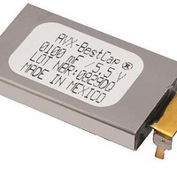
BZ015A104ZAB AVX Corporation, BZ015A104ZAB Datasheet - Page 20

BZ015A104ZAB
Manufacturer Part Number
BZ015A104ZAB
Description
Capacitor,Non-Specified,100mF,5.5VDC,20-% Tol,80+% Tol
Manufacturer
AVX Corporation
Series
BZr
Datasheet
1.BZ015B303ZSB.pdf
(26 pages)
Specifications of BZ015A104ZAB
Capacitance
0.1 Farad
Tolerance
- 20 %, 80 %
Voltage Rating
5.5 Volts
Esr
80 mOhms
Operating Temperature Range
- 20 C to + 70 C
Dimensions
17 mm W x 28 mm L x 2.1 mm H
Leakage Current
10 uAmps
Load Life
1000 Hrs
Product
Super Capacitors
Lead Free Status / Rohs Status
Lead free / RoHS Compliant
BestCap
High Power Pulse Supercapacitors
SECTION 4: APPLICATION NOTES
4.1: ELECTROCHEMICAL EDLC VS.
ELECTRONIC TECHNOLOGY -
BESTCAP
To understand the benefits offered by the BestCap
necessary to examine how an electrochemical capacitor
works. The most significant difference between an electron-
ic capacitor and an electrochemical capacitor is that the
charge transfer is carried out by the electrons in the former
and by electrons and ions in the latter. The anions and
cations involved in double layer supercapacitors are con-
tained in the electrolyte which maybe liquid, (normally an
aqueous or organic solution) or solid. The solid electrolyte is
almost universally a conductive polymer.
Electrons are relatively fast moving and therefore transfer
charge “instantly”. However, ions have to move relatively
slowly from anode to cathode, and hence a finite time is
needed to establish the full nominal capacitance of the
device. This nominal capacitance is normally measured at
1 second.
The differences between EDLC (Electrochemical Double
Layer Capacitors) and electronic capacitors are summarized
in the table below:
Cell Case (Anode)
Electrode (Cathode)
Carbon
Carbon
Cell Case (Anode)
• A capacitor basically consists of two conductive plates
• These dielectric materials may be ceramic, plastic film,
• EDLCs do not use a discrete dielectric interphase
• EDLCs utilize the charge separation, which is formed
• The EDLC constitutes of two types of charge carriers:
(electrodes), separated by a layer of dielectric material.
paper, aluminum oxide, etc.
separating the electrodes.
across the electrode – electrolyte interface.
IONIC species on the ELECTROLYTE side and
ELECTRONIC species on the ELECTRODE side.
®
CONSTRUCTION
®
Ultra-low ESR
Insulation Material
Current Collector
Separator
Current Collector
®
, it is
4.2: VOLTAGE DROP
Two factors are critical in determining the voltage drop when
a capacitor delivers a short current pulse; these are ESR
and “available” capacitance as shown in Figure 4.
The instant voltage drop ΔV
proportional to the capacitor’s ESR. The continuing voltage
drop with time ΔV
capacitance. From Figures 3 and 4, it is apparent that, for
very short current pulses, e.g. in the millisecond region, the
combination of voltage drops in a conventional supercapaci-
tor caused by a) the high ESR and b) the lack of available
capacitance, causes a total voltage drop, unacceptable for
most applications. Now compare the BestCap
under such pulse conditions. The ultra-low ESR, (in
milliOhms), minimizes the instantaneous voltage drop, while
the very high retained capacitance drastically reduces the
severity of the charge related drop. This is explained further
in a later section.
EFFICIENCY/TALKTIME BENEFITS OF BESTCAP
Because BestCap
provides a current pulse with a substantially higher voltage
than that available just from the battery as shown in Figure
5, the efficiency of the RF power amplifier is improved.
Additionally, the higher-than battery voltage supplied by the
BestCap
age” limit for a significantly longer time than is the case for
the battery alone. This increase in “talk time” is demonstrated
in Figures 6(a) (Li-Ion at +25°C), and 6(b) (Li-Ion at 0°C).
Vo
Vt
3.8
3.6
3.4
3.2
4
3
0
Figure 4. Voltage-time relation of capacitor unit
®
keeps the voltage pulse above the “cut off volt-
Battery Voltage
▲t
1000
C
, is a function of the available charge, i.e.
®
, when used in parallel with a battery,
Figure 5. GSM Pulse
Battery and Capacitor Voltage
Time (µSeconds)
▲V(IR)
ESR
2000
▲V(Q)=I* ▲ t/C(▲ t)
is caused by and is directly
▲total=I*R + I*▲t/C(▲t)
3000
Current Pulse
®
performance
4000
5
4
3
2
1
0
®
19


