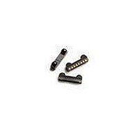
ASDL-3023-021 Avago Technologies US Inc., ASDL-3023-021 Datasheet - Page 4

ASDL-3023-021
Manufacturer Part Number
ASDL-3023-021
Description
Infrared Transceivers SFF FIR+RC Front w/o Shield
Manufacturer
Avago Technologies US Inc.
Datasheet
1.ASDL-3023-021.pdf
(25 pages)
Specifications of ASDL-3023-021
Wavelength
885 nm, 875 nm
Continual Data Transmission
4 Mbit/s
Transmission Distance
30 cm
Radiant Intensity
50 mW/sr
Half Intensity Angle Degrees
15 deg
Pulse Width
4 us, 1.6 us
Maximum Rise Time
60 ns, 600 ns
Maximum Fall Time
60 ns, 600 ns
Led Supply Voltage
- 0.3 V to 6 V
Operating Voltage
2.4 V to 3.6 V
Maximum Operating Temperature
+ 85 C
Minimum Operating Temperature
- 25 C
Dimensions
7.5 mm x 2.75 mm x 1.75 mm
Lead Free Status / RoHS Status
Lead free / RoHS Compliant
Order Information
ASDL-3023-021, ASDL-3023-008 and ASDL-3023-S21
Pinout, Rear View
Figure 2a. Pin out for ASDL-3023-021 and ASDL-3023-008,
Figure 2b. Pin out for ASDL-3023-S21
Notes:
1. Tied through external resistor, R2, to Vled. Refer to the table below for recommended series resistor value.
2. This pin is used to transmit serial data when SD pin is low. If held high for longer than 50 ms, the LED is turned off. Do NOT float this pin.
3. This pin is capable of driving a standard CMOS or TTL load. No external pull-up or pull-down resistor is required. The pin is in tri-state when the
4. Complete shutdown of IC and PIN diode. The pin is used for setting IR receiver bandwidth, range of IR LED current and RC drive programming
5. Connect to ASIC logic controller supply voltage or Vcc. The voltage at this pin should be equal to or less than Vcc.
6. Logic high turns on the RC LED. If held high longer than 50 ms, the RC LED is turned off. Do NOT float the pin.
7. (i) Regulated, 2.4V to 3.6V
8. Connect to system ground.
4
Marking Information
The unit is marked with ‘XYWLL’ on the shield
Y = year
W = work week
LL = lot number
Part Number
ASDL-0-0
ASDL-0-008
ASDL-0–S (Shielded)
8
transceiver is in shutdown mode
mode. Refer to section on “Bandwidth Selection Timing” and “Remote Control Drive Modes” for more information. Do NOT float this pin. ***
(ii) This pin recommended to turn on before other pin.
8
7
7
6
6
Rear View
Rear View
(Shielded)
5
5
4
4
3
3
2
Packaging Type
Tape and Reel
Tape and Reel
Tape and Reel
2
1
1
I/O Pins Configuration Table
Pin
4
5
6
7
8
Symbol
LEDA
TxD_IR
RxD
SD
IOVCC
TxD_RC
VCC
GND
Package
Front Option
Top Option
Front Option
Description
LED Anode
IrDA transmitter data input.
IrDA receive data
Shutdown
Input/Output ASIC voltage
RC transmitter data input.
Supply Voltage
Ground
Quantity
500
500
500
I/O Type
Input. Active High
Output. Active Low
Input. Active High
Input. Active High
Notes
Note
Note
Note
Note 4
Note 5
Note 6
Note 7
Note 8


