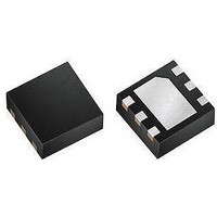
MAX9635ESA+ Maxim Integrated Products, MAX9635ESA+ Datasheet - Page 13

MAX9635ESA+
Manufacturer Part Number
MAX9635ESA+
Description
Optical Sensors - Board Mount LOW-POW AMBIENT LIGHT SENSR W/ADC
Manufacturer
Maxim Integrated Products
Datasheet
1.MAX9635EDTT.pdf
(20 pages)
Specifications of MAX9635ESA+
Supply Current
0.65 uA
Operating Supply Voltage
1.7 V to 3.6 V
Package / Case
uTDFN-6
Maximum Operating Temperature
+ 85 C
Minimum Operating Temperature
- 40 C
Lead Free Status / RoHS Status
Lead free / RoHS Compliant
Table 9. Recommended Manual Mode Settings for Configuration Register (0x02) and
Threshold Registers (0x05, 0x06)
To utilize the ultra-low power consumption of the IC in
end applications, an interrupt pin is provided to eliminate
the need for the system to poll the device continuously.
Since every clock and data bit transmitted on I
consume up to 1mA (assuming 1.8kI pullup resistor to
a 1.8V rail), minimizing the number of I
on the data bus can save a lot of power. In addition,
eliminating the need to poll the device frees up process-
ing resources for the master, improving overall system
performance.
The typical sequence of communication with the IC is
as follows:
1) Master reads lux reading from registers 0x03 and
Note: In manual mode, exceeding the lux (max) causes an overload error (exponent = 1111).
LUx LSB
0x04.
(MIN)
0.045
11.52
23.04
46.08
0.09
0.18
0.36
0.72
1.44
2.88
5.76
APPLICATION CONDITIONS
188,006
188,006
188,006
188,006
188,006
11,750
23,501
47,002
94,003
(MAx)
2938
5875
LUx
Typical Operating Sequence
LUx LSB
184.32
368.64
737.28
737.28
737.28
737.28
737.28
(MAx)
11.52
23.04
46.08
92.16
INTEGRATION
TIME (ms)
Ambient Light Sensor with ADC
2
C transactions
12.5
6.25
12.5
6.25
800
400
200
100
800
400
200
100
50
25
50
25
2
C can
RECOMMENDED SETTINGS
TIM[2:0]
Industry’s Lowest-Power
FOR CONFIGURATION
000
001
010
011
000
100
001
101
010
110
011
111
100
101
110
111
REGISTER (0x02)
2) Master sets the upper lux threshold and lower lux
3) Master sets suitable threshold timer data in register
4) Master works on other tasks until alerted by the INT
5) When alerted by the INT pin going low, the master
6) Repeat from Step 1.
threshold in registers 0x05 and 0x06 so that a user-
programmed window is defined around the current
lux readings.
0x07.
pin going low. This is where the master spends much
of its time.
reads the Interrupt Status register 0x00 to confirm
the source of interrupt was the IC. The master takes
appropriate action.
CDR
0
0
0
0
1
0
1
0
1
0
1
0
1
1
1
1
ExPONENT
RANGE OF ExPONENTS FOR
THRESHOLD REGISTERS
(MIN)
0000
0001
0010
0011
0100
0101
0110
0111
1000
1001
1010
UPPER AND LOWER
(0x05 AND 0x06)
ExPONENT
(MAx)
1000
1001
1010
1011
1100
1101
1110
1110
1110
1110
1110
13


