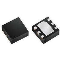
MAX9635ESA+ Maxim Integrated Products, MAX9635ESA+ Datasheet - Page 8

MAX9635ESA+
Manufacturer Part Number
MAX9635ESA+
Description
Optical Sensors - Board Mount LOW-POW AMBIENT LIGHT SENSR W/ADC
Manufacturer
Maxim Integrated Products
Datasheet
1.MAX9635EDTT.pdf
(20 pages)
Specifications of MAX9635ESA+
Supply Current
0.65 uA
Operating Supply Voltage
1.7 V to 3.6 V
Package / Case
uTDFN-6
Maximum Operating Temperature
+ 85 C
Minimum Operating Temperature
- 40 C
Lead Free Status / RoHS Status
Lead free / RoHS Compliant
Industry’s Lowest-Power
Ambient Light Sensor with ADC
Interrupt events set the INTS bit (register 0x00, bit 0) and the INT pin only if the INTE bit is set to 1. If the INTE bit is set
(interrupt is enabled) and the interrupt condition is triggered, then the INT pin is pulled low (asserted) and the INTS bit
in the Interrupt Status register is set to 1. See Table 3.
Table 3. Interrupt Enable Register
Table 4. Continuous Mode Register
Note: Continuous mode is independent of the manual configuration mode setting.
In automatic mode (MANUAL = 0), reading the contents of TIM[2:0] and CDR bits reflects the automatically generated
values from an internal timing register and are read-only. In manual mode (MANUAL = 1), the contents of TIM[2:0] and
CDR bits can be modified by the users through the I
Table 5. Manual Configuration Register
The CDR bit controls the current division ratio. The photodiode current is divided as shown in Table 6.
Table 6. Current Division Ratio Register
8
CONT
BIT 7
BIT 0
BIT 7
BIT 6
BIT 3
0
1
0
1
0
1
0
1
MANUAL
BIT 6
The INT pin and the INTS bit are not asserted even if an interrupt event has occurred.
Detection of an interrupt event triggers a hardware interrupt (INT pin is pulled low) and sets the INTS bit
(register 0x00, bit 0).
Default mode. The IC measures lux intensity only once every 800ms regardless of integration time. This
mode allows the part to operate at its lowest possible supply current.
Continuous mode. The IC continuously measures lux intensity. That is, as soon as one reading is finished, a
new one begins. If integration time is 6.25ms, readings are taken every 6.25ms. If integration time is 800ms,
readings are taken every 800ms. In this mode, the part consumes slightly higher power than in the default
mode.
Default mode of configuration is used for the IC. In this mode, CDR and TIM[2:0] bits are automatically deter-
mined by the internal autoranging circuitry of the IC.
Manual mode of configuration is used for the IC. In this mode, CDR and TIM[2:0] bits can be programmed
by the user.
Current not divided. All of the photodiode current goes to the ADC.
Current divided by 8. Only 1/8 of the photodiode current goes to the ADC. This mode is used in
high-brightness situations.
BIT 5
—
BIT 4
—
2
C bus.
BIT 3
CDR
OPERATION
OPERATION
OPERATION
OPERATION
BIT 2
TIM[2:0]
BIT 1
Current Division Ratio (CDR)
Manual Configuration Mode
Configuration 0x02
BIT 0
Continuous Mode
REGISTER
ADDRESS
0x02


