6-531396-0 TE Connectivity, 6-531396-0 Datasheet - Page 53
6-531396-0
Manufacturer Part Number
6-531396-0
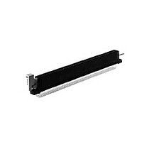
Description
CONN ZIF II 100 C/L 65 POS R/A
Manufacturer
TE Connectivity
Type
Card Edger
Datasheet
1.6-531396-0.pdf
(96 pages)
Specifications of 6-531396-0
Number Of Contacts
130POS
Body Orientation
Right Angle
Contact Plating
Nickel
Contact Material
Phosphor Bronze
Termination Method
Solder
Mounting Style
Through Hole
Pitch (mm)
2.54mm
Housing Material
Polyester
Product Type
Connector
Pcb Mounting Orientation
Right Angle
Termination Method To Pc Board
Through Hole - Solder
Number Of Dual Positions
65
Housing Style
Closed End/Open End
Pcb Mount Alignment
Without
Pcb Mount Retention
With
Zif Actuator Style
Rotary Cam ZIF
Bend Side
Right
Qty./tray
25
Boardlock
With
Centerline (mm [in])
2.54 [0.100]
Row-to-row Spacing (mm [in])
5.08 [0.200]
Pcb Mount Retention Type
Mounting Ears
Post Plating
Matte Tin
Contact Base Material
Phosphor Bronze
Contact Plating, Mating Area, Material
Gold (30)
Underplate Material
Nickel
Ul Flammability Rating
UL 94V-0
Card Retention
With
Card Retention Type
Rotary Cam ZIF, With Board Lock
Rohs/elv Compliance
RoHS compliant, ELV compliant
Lead Free Solder Processes
Wave solder capable to 240°C
Rohs/elv Compliance History
Always was RoHS compliant
Agency/standard
UL
Operating Temperature (°c [°f])
-55 – +105 [-67 – +221]
Applies To
Printed Circuit Board
Accepts Card Thickness (mm [in])
1.37 – 1.78 [0.054 – 0.070]
Lead Free Status / RoHS Status
Compliant


Catalog 1654080
Issued 7-03
www.tycoelectronics.com
Product Facts
Physical Properties:
Insulation Resistance—
5000 megohms minimum.
Insertion/Withdrawal Force
(Daughter Card)—8 oz./2 oz.
[35.6 N/ 8.9 N] average contact pair
using .0620 [1.57] steel blade.
Insulator Body—Glass filled
thermoplastic, UL rating 94V-O. High
temp. plastic option is available; add
suffix M399 to part number.
Color—Black
Contacts—High strength copper alloy.
Contact Plating—.000050 [0.00127]
nickel underplate with .000030
[0.00076] gold in the mating area,
tin/lead on tails, .000100 [0.00254]
minimum
Electrical Properties:
Operation Voltage—1500 VDC
(sea level)
Current Rating—3 Amperes
Initial Contact Resistance—
10 milliohms
Environmental Properties:
Operating Temperature—
-55˚C to +125˚C
Temperature Cycling—
MIL-STD-202 method 107
Vibration—MIL-STD-202 method 204
Related Product Data:
Polarization Key—page 57
Daughter Card Edge Pattern—
page 57
Recognized under the
Component Program
of Underwriters
Laboratories Inc.,
File No. E60980
Certified
by Canadian
Standards
Association,
File No. LR49571
Dimensions are in inches and
millimeters unless otherwise
specified. Values in brackets
are metric equivalents.
Card Edge Connectors
(Solder Type, Board-to-Board)
Modified Bellows Connectors, .156 x .200 [3.96 x 5.08] Centerline, Straight
Dip Solder and Wire Wrap Ta i l s
[6.35]
.250
[9.35]
.368
[4.57]
.180
[3.25]
.128
Dimensions are shown for
reference purposes only.
Specifications subject
to change.
Dia.
Centered Mounting Ear
.125 [3.18] Thru Hole
[3.25]
.156
[15.49]
.610
A
P±.003 [.08] Dia.
Mounting Styles
USA: 1-800-522-6752
Canada: 1-905-470-4425
Mexico: 01-800-733-8926
C. America: 52-55-5-729-0425
P=.040 [1.02] Dip Solder Applications
P=.042 [1.07] For Wire Wrap Applications
Ref.
[3.96]
.156
C
Centered Mounting Ear
Ref.
4-40 Threaded Insert
Dim E
B
Dim B
D
ROTATED 90º
SECTION X-X
SECTION X-X
.025
[.64]
E
[5.49]
.610
Sq.
South America: 55-11-3611-1514
Hong Kong: 852-2735-1628
Japan: 81-44-844-8013
UK: 44-141-810-8967
[5.08]
.200
[5.08]
.200
No Mounting Ears
[1.37±1.890 ] PC Board
.054±.071
[7.62] Card Depth
.300
J
53
Related parts for 6-531396-0
Image
Part Number
Description
Manufacturer
Datasheet
Request
R

Part Number:
Description:
Manufacturer:
IDT, Integrated Device Technology Inc
Datasheet:

Part Number:
Description:
Manufacturer:
IDT, Integrated Device Technology Inc
Datasheet:
Part Number:
Description:
Manufacturer:
IDT, Integrated Device Technology Inc
Datasheet:
Part Number:
Description:
Manufacturer:
IDT, Integrated Device Technology Inc
Datasheet:
Part Number:
Description:
Manufacturer:
IDT, Integrated Device Technology Inc
Datasheet:

Part Number:
Description:
FASTIN-FASTON RECEP 6,35
Manufacturer:
TE Connectivity
Datasheet:

Part Number:
Description:
Conn Shielded Circular Subminiature PIN 5 POS Solder ST Thru-Hole 5 Terminal 1 Port
Manufacturer:
TE Connectivity
Datasheet:

Part Number:
Description:
Manufacturer:
TE Connectivity
Datasheet:

Part Number:
Description:
PLUG, SOLARLOK, 6MM, POS
Manufacturer:
TE Connectivity
Datasheet:
Part Number:
Description:
PLUG, SOLARLOK, 6MM, NEG
Manufacturer:
TE Connectivity
Datasheet:

Part Number:
Description:
6-1415035-1
Manufacturer:
TE Connectivity
Datasheet:

Part Number:
Description:
Manufacturer:
TE Connectivity
Datasheet:

Part Number:
Description:
Conn Shielded Circular Subminiature SKT 3 POS Solder ST Thru-Hole 3 Terminal 1 Port
Manufacturer:
TE Connectivity
Datasheet:

Part Number:
Description:
TERMINAL, SOCKET, FASTON, 18-15AWG
Manufacturer:
TE Connectivity
Datasheet:

Part Number:
Description:
Manufacturer:
TE Connectivity
Datasheet: