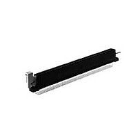
6-531396-0 TE Connectivity, 6-531396-0 Datasheet - Page 95

6-531396-0
Manufacturer Part Number
6-531396-0
Description
CONN ZIF II 100 C/L 65 POS R/A
Manufacturer
TE Connectivity
Type
Card Edger
Datasheet
1.6-531396-0.pdf
(96 pages)
Specifications of 6-531396-0
Number Of Contacts
130POS
Body Orientation
Right Angle
Contact Plating
Nickel
Contact Material
Phosphor Bronze
Termination Method
Solder
Mounting Style
Through Hole
Pitch (mm)
2.54mm
Housing Material
Polyester
Product Type
Connector
Pcb Mounting Orientation
Right Angle
Termination Method To Pc Board
Through Hole - Solder
Number Of Dual Positions
65
Housing Style
Closed End/Open End
Pcb Mount Alignment
Without
Pcb Mount Retention
With
Zif Actuator Style
Rotary Cam ZIF
Bend Side
Right
Qty./tray
25
Boardlock
With
Centerline (mm [in])
2.54 [0.100]
Row-to-row Spacing (mm [in])
5.08 [0.200]
Pcb Mount Retention Type
Mounting Ears
Post Plating
Matte Tin
Contact Base Material
Phosphor Bronze
Contact Plating, Mating Area, Material
Gold (30)
Underplate Material
Nickel
Ul Flammability Rating
UL 94V-0
Card Retention
With
Card Retention Type
Rotary Cam ZIF, With Board Lock
Rohs/elv Compliance
RoHS compliant, ELV compliant
Lead Free Solder Processes
Wave solder capable to 240°C
Rohs/elv Compliance History
Always was RoHS compliant
Agency/standard
UL
Operating Temperature (°c [°f])
-55 – +105 [-67 – +221]
Applies To
Printed Circuit Board
Accepts Card Thickness (mm [in])
1.37 – 1.78 [0.054 – 0.070]
Lead Free Status / RoHS Status
Compliant
Tooling
.100 x .100 [2.54 x 2.54] Centerline Connectors
.125 x .125 [3.18 x 3.18] Centerline Connectors
Catalog 1654080
Issued 7-03
www.tycoelectronics.com
Positions
Positions
No. of
No. of
Dual
Dual
100
112
124
140
110
115
120
125
140
175
50
80
40
52
56
60
72
84
Applicator
Applicator
266267-4
266267-3
266267-4
266267-5
266267-5
266267-5
266267-4
266267-4
266267-5
313139-1
313139-2
313139-2
313139-2
313139-3
313139-2
313139-2
313139-2
313139-2
T-Bar
T-Bar
Dimensions are in inches and
millimeters unless otherwise
specified. Values in brackets
are metric equivalents.
Removal
265924-4
265924-4
265924-4
265924-4
265924-4
265924-4
265924-4
265924-4
265924-4
Removal
265924-4
265924-6
265924-6
265924-7
265924-4
265924-5
265924-7
265924-5
265924-5
Carrier
Carrier
Tool
Tool
Assembly tooling is not
required except when
using connectors with
ACTION PIN contacts.
ACTION PIN contact
assembly requires an
arbor-style bench tool with a
capacity of 40 lb [178 N] per
contact, a support fixture,
contact applicator, carrier
removal tool and housing
assembly tool.
Card Edge Connectors
(Solder Type, Board-to-Board)
Linear ZIF Connectors
Assembly
Assembly
313136-1
313136-2
313136-3
313136-4
313136-5
313136-1
313136-2
313136-3
313136-4
313136-5
Housing
Housing
Tool
Tool
Dimensions are shown for
reference purposes only.
Specifications subject
to change.
Removal
313256-1
Removal
313256-1
Housing
Housing
Tool
Tool
(Continued)
Typical procedure is to
place a PC board on the
support fixture, insert contact
combs into the printed circuit
board with the contact appli-
cator and seat with the arbor
tool. Next, remove the carrier
strip from the contact combs
with the carrier break-off tool.
Place the housing over the
contacts with the housing
assembly tool, and repeat
the entire process until the
board is complete.
Wing Removal/
Wing Removal/
Replacement
Replacement
266233-1
266233-1
Tool
Tool
USA: 1-800-522-6752
Canada: 1-905-470-4425
Mexico: 01-800-733-8926
C. America: 52-55-5-729-0425
Insertion
266264-1
Insertion
266264-1
Housing
Housing
Tool
Tool
With Housing
With Housing
266235-1
266235-1
Contact Replacement Tools
Contact Replacement Tools
South America: 55-11-3611-1514
Hong Kong: 852-2735-1628
Japan: 81-44-844-8013
UK: 44-141-810-8967
Without Housing
Without Housing
3-265871-2
3-265871-2
95


