XR21V1410IL-0C-EB Exar Corporation, XR21V1410IL-0C-EB Datasheet
XR21V1410IL-0C-EB
Specifications of XR21V1410IL-0C-EB


Related parts for XR21V1410IL-0C-EB

XR21V1410IL-0C-EB Summary of contents
Page 1
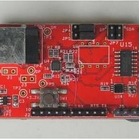
REV. 1.0.0 1.0 INTRODUCTION This user’s manual is for the XR21V1410 evaluation board. It will describe the hardware setup required to operate the part. 2.0 OVERVIEW The XR21V1410 evaluation board has one 16-QFN package on it. evaluation board layout. F ...
Page 2
... ABLE OMPONENTS U L NIT OCATION U1 Top SP6669AEK-L/TRR3 Exar’s Voltage converter to step down voltage from 5V to 3.3V. U2 Bottom SN74LVC2G53DCTR Multiplexer to switch between RS-232 and RS-485 mode Top XR21V1410IL16-F U5 Bottom NC7SZ14M5X U6 Top AT24C02B U7 Top SP3245EEY-L U8 Bottom SN74LVC2G66DCT U9 Top SP3497EEN-L CON1 Top ...
Page 3
REV. 1.0 ABLE OMPONENTS U L NIT OCATION CON2 Top 690-004-621-023 CON3 Top 182-009-113R161 CON4 Top ED555/4DS N :1) An external pull-up is required on the LOWPOWER pin for proper functionality. The external pull-up is not shown ...
Page 4
XR21V1410 EVALUATION BOARD USER’S MANUAL 2.2.2 Remote wakeup and jumper The SDA and SCL are used to specify whether Remote Wakeup and/or Bus Powered configurations are to be supported. These pins are sampled at power-up. The following Bus Powered support. ...
Page 5
... For any questions about this evaluation board, software drivers or technical support, send an e-mail to uarttechsupport@exar.com. EXAR Corporation reserves the right to make changes to the products contained in this publication in order to improve design, performance or reliability. EXAR Corporation assumes no responsibility for the use of any circuits described herein, conveys no license under any patent or other right, and makes no representation that the circuits are free of patent infringement. Charts and schedules contained here in are only for illustration purposes and may vary depending upon a user’ ...