33000 Parallax Inc, 33000 Datasheet - Page 17
33000
Manufacturer Part Number
33000
Description
Power Management Modules & Development Tools 30W Solar Cell Kit
Manufacturer
Parallax Inc
Datasheet
1.33000.pdf
(20 pages)
Specifications of 33000
New! Us2012 Catalog Page
Solar Cells_Panels
Voltage - Output
*
Operating Temperature
*
Current Short Circuit (isc)
*
Package / Case
-
Lead Free Status / RoHS Status
Lead free / RoHS Compliant
Available stocks
Company
Part Number
Manufacturer
Quantity
Price
Company:

Part Number:
33000-0001
Manufacturer:
MOLEX
Quantity:
43 635
Company:
Part Number:
33000-0001
Manufacturer:
MOLEX
Quantity:
35 000
Company:
Part Number:
33000-0002
Manufacturer:
MOLEX
Quantity:
25 000
Company:
Part Number:
33000-0002
Manufacturer:
STARCONN
Quantity:
12 450
Company:
Part Number:
33000-0003
Manufacturer:
MOLEX
Quantity:
43 637
Part Number:
330000001
Manufacturer:
MOLEX
Quantity:
20 000
Part Number:
330000002
Manufacturer:
MOLEX
Quantity:
20 000


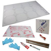
Step 11 — Checking cell clearances within the Base Panel
Section E – Sealing the Panel
As mentioned earlier, the Base Panel is slightly bowed because of the machining process. Once the
Cover is cemented to the Base Panel, the bow will be removed and the Panel will become quite rigid.
Cementing the panels together is a critical part of the assembly process.
polycarbonate cement manufacturer’s precautions and recommendations on the tube label.
The cement is a “solvent weld” type which means that it chemically melts the two surfaces of the panels
together (very similar to the white PVC water pipe cementing process). By melting the Base and Cover
Panels together the finished panel becomes a very strong and protective encapsulation for the delicate
cells. However, once you seal the panel, you’ll never be able to access the cells again. Be sure
that you’re pleased with the solder connections and the performance of the panel before you commit to
sealing it.
As shown in Figure 35, there will be a single continuous bead of cement running around the outside
perimeter of the Base Panel, to form a complete seal.
It is also important to note that cement does cause a “frost” or opaqueness to the panels wherever it is
applied, so you want to use just enough to make a good joint, but not enough to spill over into the cell
cavities and obscure too much of the adjacent cells. A little bit of obscurity is ok, just don’t flood it.
Copyright © Parallax Inc.
Remove the protective film from both sides of the 1/8” thick Cover Panel.
Carefully place the Cover Panel over the Base Panel to check whether or not the cells and solder
connections are recessed enough into their cavities to clear the cover, as shown in Figure 34.
If anything does interfere, re-flow the solder connections as required to create the necessary
clearance. To re-flow any “blobs,” simply add flux to the problem area, add a little solder to your
iron and wipe gently, smoothing out the imperfections. REMINDER: don’t use flux remover! The
rapid evaporation may cause the cell to flex and break. Flux on the front of the cell won’t
significantly lower power output.
30 Watt Solar Panel Kit (#33000)
Figure 34
v1.0 2/19/2010 Page 17 of 20
Be sure to follow all
Related parts for 33000
Image
Part Number
Description
Manufacturer
Datasheet
Request
R


Part Number:
Description:
Microcontroller Modules & Accessories DISCONTINUED BY PARALLAX
Manufacturer:
Parallax Inc

Part Number:
Description:
BOOK UNDERSTANDING SIGNALS
Manufacturer:
Parallax Inc
Datasheet:


Part Number:
Description:
COMPETITION RING FOR SUMOBOT
Manufacturer:
Parallax Inc
Datasheet:


Part Number:
Description:
TEXT INFRARED REMOTE FOR BOE-BOT
Manufacturer:
Parallax Inc
Datasheet:
Part Number:
Description:
BOARD EXPERIMENT+LCD NX-1000
Manufacturer:
Parallax Inc
Datasheet:

Part Number:
Description:
CONTROLLER 16SERVO MOTOR CONTROL
Manufacturer:
Parallax Inc
Datasheet:

Part Number:
Description:
BASIC STAMP LOGIC ANALYZER
Manufacturer:
Parallax Inc
Datasheet:

Part Number:
Description:
IC MCU 2K FLASH 50MHZ SO-18
Manufacturer:
Parallax Inc
Datasheet: