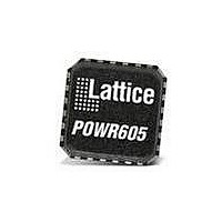
PAC-POWR607-EV Lattice, PAC-POWR607-EV Datasheet

PAC-POWR607-EV
Specifications of PAC-POWR607-EV
Related parts for PAC-POWR607-EV
PAC-POWR607-EV Summary of contents
Page 1
... Evaluation Board User’s Guide May 2007 Revision: EB28_01.0 ...
Page 2
... Programming is performed via the industry-standard JTAG IEEE 1149.1 interface. PAC-POWR607-EV Evaluation Board The PAC-POWR607-EV evaluation board (Figure 1) allows the designer to quickly configure and evaluate the isp- PAC-POWR607 device on a fully assembled printed-circuit board. The board supports a 32-pin QFN package, pads for user I/O, a JTAG programming cable connector, LEDs and switches ...
Page 3
... The kit comes with a battery and cable that plugs into the connector at J2 and provides power with a 9V battery, see Figure desired to test the current in the power down mode of the ispPAC-POWR607, the link between pins 3 and should be cut (please refer to Appendix A). Otherwise, approximately 2mA will be drawn when the device is in power down mode ...
Page 4
... Momentary push-button switches 1 U1 ispPAC-POWR607 3.3V LDO REG SOIC 1 N/A PCB 2” by 3.5” Ordering Information • Part Number: PAC-POWR607-EV References • ispPAC-POWR607 Data Sheet Technical Support Assistance Hotline: 1-800-LATTICE (North America) +1-503-268-8001 (Outside North America) e-mail: isppacs@latticesemi.com Internet: www.latticesemi.com Revision History Date May 2007 © ...
Page 5
... Lattice Semiconductor Appendix A. Schematics The following figures comprise the schematics for the ispPAC-POWR607 evaluation board. Figure 3 shows the device schematic and JTAG interface, while Figure 4 shows the on-board power-supply circuitry and the LED dis- play. Figure 3. ispPAC-POWR607 Device Schematic Evaluation Board User’s Guide ...
Page 6
... Lattice Semiconductor Figure 4. Power Supply and LEDs Enb 2 GND 1 Evaluation Board User’s Guide 6 ispPAC-POWR607 ...


