D3172MMA7361LC Freescale Semiconductor, D3172MMA7361LC Datasheet - Page 15
D3172MMA7361LC
Manufacturer Part Number
D3172MMA7361LC
Description
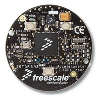
Acceleration Sensor Development Tools XYZ-AXIS DIGITAL ACCEL D
Manufacturer
Freescale Semiconductor
Specifications of D3172MMA7361LC
Acceleration
1.5 g
Sensing Axis
Triple Axis
Output Type
Digital
Interface Type
I2C, SPI
Operating Voltage
2 V to 3.4 V
Operating Current
47 uA
Sensitivity
64 LSB/g
For Use With/related Products
MMA7660FC
Lead Free Status / RoHS Status
Lead free / RoHS Compliant


ASSIGNING, CLEARING & DETECTING INTERRUPTS
Assigning the interrupt pins is done in Register $18. There are 3 combinations for the interrupt pins to be assigned which are
outlined below in the table for INTREG[1:0].
Table 7. Configuring the Interrupt settings using Register $18 with INTREG[1:0] bits
00: INT1 Register is detecting Level while INT2 is detecting Pulse.
01: INT1 Register is detecting Pulse while INT2 is detecting Level.
10: INT1 Register is detecting a Single Pulse and INT2 is detecting Single Pulse (if 2
time window and second time window > 0 then INT2 will detect the double pulse only.
INTPIN: INT1 pin is routed to INT1 bit in Detection Source Register ($0A) and INT2 pin is routed to INT2 bit in Detection Source
Register ($0A).
INTPIN: INT2 pin is routed to INT1 bit in Detection Source Register ($0A) and INT1 pin is routed to INT2 bit in Detection Source
Register ($0A).
Note: When INTREG[1:0] =10 for the condition to detect single pulse on INT1 and either single or double pulse on INT2, INT1
register bit can no longer be cleared by setting CLR_INT1 bit. It is cleared by setting CLR_INT2 bit. In this case, setting CLR_INT2
clears both INT1 and INT2 register bits and resets the detection operation. Follow the example given for clearing the interrupts.
Clearing the Interrupt Pins: Register $17
CLR_INT1
1: Clear “INT1”
0: Do not clear “INT1”
CLR_INT2
1: Clear “INT2”
0: Do not clear “INT2”
After interrupt has triggered due to a detection, the interrupt pin (INT1 or INT2) need to be cleared by writing a logic 1. Then the
interrupt pin should be enabled to trigger the next detection by setting it to a logic 0.
This example is to show how to reset the interrupt flags
void ClearIntLatch(void)
{
IIC_ByteWrite(INTRST, 0x03);
IIC_ByteWrite(INTRST, 0x00);
}
$18 Control 1 Register
$17: Interrupt Latch Reset (Read/Write)
Sensors
Freescale Semiconductor
DFBW
D7
D7
0
--
0
INTREG[1:0]
00
01
10
THOPT
D6
D6
--
0
0
ZDA
D5
D5
--
0
0
Single Pulse detection
“INT1” Register Bit
Pulse Detection
Level detection
YDA
D4
D4
--
0
0
XDA
D3
D3
--
0
0
INTREG[1]
D2
D2
--
0
0
nd
INTREG[0]
Time Window = 0) or if there is a latency
CLR_INT2
Single or Double Pulse Detection
D1
D1
0
0
“INT2” Register Bit
Pulse Detection
Level Detection
CLR_INT1
INTPIN
D0
D0
0
0
MMA7455L
Function
Function
Reg $18
Reg $17
Default
Default
15
Related parts for D3172MMA7361LC
Image
Part Number
Description
Manufacturer
Datasheet
Request
R

Part Number:
Description:
Manufacturer:
Freescale Semiconductor, Inc
Datasheet:
Part Number:
Description:
Manufacturer:
Freescale Semiconductor, Inc
Datasheet:
Part Number:
Description:
Manufacturer:
Freescale Semiconductor, Inc
Datasheet:
Part Number:
Description:
Manufacturer:
Freescale Semiconductor, Inc
Datasheet:
Part Number:
Description:
Manufacturer:
Freescale Semiconductor, Inc
Datasheet:
Part Number:
Description:
Manufacturer:
Freescale Semiconductor, Inc
Datasheet:
Part Number:
Description:
Manufacturer:
Freescale Semiconductor, Inc
Datasheet:
Part Number:
Description:
Manufacturer:
Freescale Semiconductor, Inc
Datasheet:
Part Number:
Description:
Manufacturer:
Freescale Semiconductor, Inc
Datasheet:
Part Number:
Description:
Manufacturer:
Freescale Semiconductor, Inc
Datasheet:
Part Number:
Description:
Manufacturer:
Freescale Semiconductor, Inc
Datasheet:
Part Number:
Description:
Manufacturer:
Freescale Semiconductor, Inc
Datasheet:
Part Number:
Description:
Manufacturer:
Freescale Semiconductor, Inc
Datasheet:
Part Number:
Description:
Manufacturer:
Freescale Semiconductor, Inc
Datasheet:
Part Number:
Description:
Manufacturer:
Freescale Semiconductor, Inc
Datasheet: