2-531414-4 TE Connectivity, 2-531414-4 Datasheet - Page 42
2-531414-4
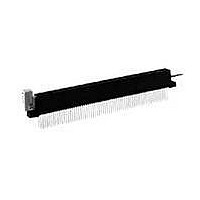
Manufacturer Part Number
2-531414-4
Description
FFC / FPC Connectors CONN ZIF II 100 C/L 50 POS
Manufacturer
TE Connectivity
Type
Card Edger
Datasheet
1.2-531414-4.pdf
(96 pages)
Specifications of 2-531414-4
Number Of Contacts
100POS
Body Orientation
Straight
Contact Material
Phosphor Bronze
Termination Method
Solder
Mounting Style
Through Hole
Product Type
Connector
Pcb Mounting Orientation
Vertical
Termination Method To Wire/cable
Wire Wrap
Termination Method To Pc Board
Through Hole - Solder
Number Of Dual Positions
50
Housing Style
Closed End/Open End
Pcb Mount Alignment
Without
Pcb Mount Retention
With
Zif Actuator Style
Rotary Cam ZIF
Qty./tray
25
Boardlock
With
Termination Post Length (mm [in])
14.73 [0.580]
Centerline (mm [in])
2.54 [0.100]
Row-to-row Spacing (mm [in])
5.08 [0.200]
Pcb Mount Retention Type
Mounting Ears
Post Plating
Tin-Lead (100)
Contact Base Material
Phosphor Bronze
Contact Plating, Mating Area, Material
Gold (30)
Underplate Material
Nickel
Housing Material
Polyester GF
Ul Flammability Rating
UL 94V-0
Card Retention
With
Card Retention Type
Rotary Cam ZIF, With Board Lock
Rohs/elv Compliance
RoHS compliant, ELV compliant
Lead Free Solder Processes
Wave solder capable to 240°C
Rohs/elv Compliance History
Always was RoHS compliant
Agency/standard
UL
Operating Temperature (°c [°f])
-55 – +105 [-67 – +221]
Applies To
Printed Circuit Board, Wire/Cable
Accepts Card Thickness (mm [in])
1.37 – 1.78 [0.054 – 0.070]
Lead Free Status / RoHS Status
Compliant


42
Product Facts
Physical Properties:
Insulation Resistance—5000
megohms minimum.
Insertion/Withdrawal Force
(Daughter Card)—8 oz./2 oz.
[35.6 N/ 8.9 N] average contact pair
using .0620 [1.57] steel blade.
Insulator Body—Glass filled
thermoplastic, UL rating 94V-O. High
temp. plastic option is available; add
suffix M399 to part number.
Color—Black
Contacts—High strength copper alloy.
Contact Plating—.000050 [0.00127]
nickel underplate with .000030
[0.00076] gold in the mating area,
tin/lead on tails, .000100 [0.00254]
minimum
Electrical Properties:
Operation Voltage—600 VDC
(sea level)
Current Rating—3 Amperes
Initial Contact Resistance—
10 milliohms
Environmental Properties:
Operating Temperature—
-55˚C to +125˚C
Temperature Cycling—
MIL-STD-202 method 107
Vibration—MIL-STD-202 method 204
Related Product Data:
Polarization Key—page 57
Daughter Card Edge Pattern—
page 57
Catalog 1654080
Issued 7-03
www.tycoelectronics.com
Recognized under the
Component Program
of Underwriters
Laboratories Inc.,
File No. E60980
Certified
by Canadian
Standards
Association,
File No. LR49571
[6.35]
.250
[4.57]
.180
Centered Mounting Ear
.125 [3.18] Thru Hole
Dimensions are in inches and
millimeters unless otherwise
specified. Values in brackets
are metric equivalents.
[15.49]
.610
Ref.
Card Edge Connectors
(Solder Type, Board-to-Board)
Modified Bellows Connectors .100 x .200 [2.54 x 5.08], Straight Dip
Solder And Wire Wrap Tails
Centered Mounting Ear
4-40 Threaded Insert
[9.53]
[3.25] Dia.
.368
.128
Dimensions are shown for
reference purposes only.
Specifications subject
to change.
.100
[2.54]
.100
Mounting Styles
No Mounting Ears
A
P=.040 [1.02] Dip Solder Applications
P=.042 [1.07] For Wire Wrap Applications
[2.54] Ref.
.100
USA: 1-800-522-6752
Canada: 1-905-470-4425
Mexico: 01-800-733-8926
C. America: 52-55-5-729-0425
C
Dim E
B
Dim B
D
SECTION X-X
.125 [3.18] Thru Hole
Flush Mounting Ear
E
ROTATED 90º
SECTION X-X
.025
[.64]
[15.49]
.610
Sq
[5.08]
.200
South America: 55-11-3611-1514
Hong Kong: 852-2735-1628
Japan: 81-44-844-8013
UK: 44-141-810-8967
[5.08]
.200
4-40 Threaded Insert
Flush Mounting Ear
[1.37 - 1.80] P.C. Board
.054 - .071
[7.62] Card Depth
.300
J
Related parts for 2-531414-4
Image
Part Number
Description
Manufacturer
Datasheet
Request
R

Part Number:
Description:
SWITCH, ROTARY, DPST, 3A, 125V
Manufacturer:
Honeywell Sensing and Control
Datasheet:

Part Number:
Description:
Manufacturer:
TE Connectivity
Datasheet:

Part Number:
Description:
RF (Radio Frequency) Relays HI FREQ SPDT 50 OHM 140MW 5V MONO
Manufacturer:
Tyco Electronics
Datasheet:

Part Number:
Description:
TERMINAL,PIDG R IR 14 5/16
Manufacturer:
TE Connectivity
Datasheet:

Part Number:
Description:
BATTERY SW N-CH 30V 3.4A 8-TSSOP
Manufacturer:
Vishay
Datasheet:
Part Number:
Description:
RES 220 OHM 1W 5% 2512
Manufacturer:
TE Connectivity
Datasheet:

Part Number:
Description:
Manufacturer:
TE Connectivity
Datasheet:

Part Number:
Description:
CONNECTOR, 5WAY, R/A, 2
Manufacturer:
TE Connectivity
Datasheet:

Part Number:
Description:
WIRE-BOARD CONN RECEPTACLE 10POS, 1.27MM
Manufacturer:
TE Connectivity
Datasheet:
Part Number:
Description:
INDUCTOR 680NH 500MA 1812
Manufacturer:
TE Connectivity
Datasheet:

Part Number:
Description:
Manufacturer:
TE Connectivity
Datasheet:

Part Number:
Description:
Manufacturer:
TE Connectivity
Datasheet:


Part Number:
Description:
WIRE-BOARD CONN, HEADER, 14POS, 2.54MM
Manufacturer:
TE Connectivity
Datasheet:

Part Number:
Description:
Conn Shrouded Header HDR 14 POS 2.54mm Solder ST Thru-Hole
Manufacturer:
TE Connectivity
Datasheet: