2-531414-4 TE Connectivity, 2-531414-4 Datasheet - Page 57
2-531414-4
Manufacturer Part Number
2-531414-4
Description
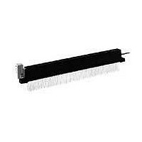
FFC / FPC Connectors CONN ZIF II 100 C/L 50 POS
Manufacturer
TE Connectivity
Type
Card Edger
Datasheet
1.2-531414-4.pdf
(96 pages)
Specifications of 2-531414-4
Number Of Contacts
100POS
Body Orientation
Straight
Contact Material
Phosphor Bronze
Termination Method
Solder
Mounting Style
Through Hole
Product Type
Connector
Pcb Mounting Orientation
Vertical
Termination Method To Wire/cable
Wire Wrap
Termination Method To Pc Board
Through Hole - Solder
Number Of Dual Positions
50
Housing Style
Closed End/Open End
Pcb Mount Alignment
Without
Pcb Mount Retention
With
Zif Actuator Style
Rotary Cam ZIF
Qty./tray
25
Boardlock
With
Termination Post Length (mm [in])
14.73 [0.580]
Centerline (mm [in])
2.54 [0.100]
Row-to-row Spacing (mm [in])
5.08 [0.200]
Pcb Mount Retention Type
Mounting Ears
Post Plating
Tin-Lead (100)
Contact Base Material
Phosphor Bronze
Contact Plating, Mating Area, Material
Gold (30)
Underplate Material
Nickel
Housing Material
Polyester GF
Ul Flammability Rating
UL 94V-0
Card Retention
With
Card Retention Type
Rotary Cam ZIF, With Board Lock
Rohs/elv Compliance
RoHS compliant, ELV compliant
Lead Free Solder Processes
Wave solder capable to 240°C
Rohs/elv Compliance History
Always was RoHS compliant
Agency/standard
UL
Operating Temperature (°c [°f])
-55 – +105 [-67 – +221]
Applies To
Printed Circuit Board, Wire/Cable
Accepts Card Thickness (mm [in])
1.37 – 1.78 [0.054 – 0.070]
Lead Free Status / RoHS Status
Compliant


Catalog 1654080
Issued 7-03
www.tycoelectronics.com
Description/Application
Tyco Electronics can pro-
vide polarization keys in the
basic configuration shown
on this page. Our Modified
Bellows and Cantilever
Beam Series Card Edge
Connectors use these keys.
The part number and the
connector series for which it
was designed are listed in
the table below.
Per MIL-C-21097E
Dimensions are in inches and
millimeters unless otherwise
specified. Values in brackets
are metric equivalents.
Card Edge Connectors
(Solder Type, Board-to-Board)
Ordering Information
Card Edge Polarization Keys
Card Edge Connectors Recommended Daughter Card Edge Pattern
Daughter Card
* Except MIL-C-21097E 8–4 which is .070 [1.78]
NOTES:
1. Dimensions are in inches
2. Unless otherwise specified, tolerance is ±.005 [0.13 mm] for three place
3. Number of contact fingers shall be the same as the corresponding printed
Acquired Part
decimals.
wiring connector.
Slot Depth
Dim. A
98014-01
98014-01
Contact Spacing
Number
Min.
Non-Accum.
.100 [2.54]
.125 [3.18]
.156 [3.96]
.033
[.84]
Dimensions are shown for
reference purposes only.
Specifications subject
to change.
Break Off Point
Used on Connector
.105* [2.67]
±.005 (.13)
.093 [2.36]
.093 [2.36]
Modified Bellows
Cantilever Beam
Dim A
(Per Applicable Catalog Page)
Series
Dim. B
See Note 3
Contact Spacing
USA: 1-800-522-6752
Canada: 1-905-470-4425
Mexico: 01-800-733-8926
C. America: 52-55-5-729-0425
[4.83]
.19
.052 [1.32]
.052 [1.32]
.094 [2.39]
Dim B
Shown on
Pages
41-56
28-40
45°
[6.10]
.24
South America: 55-11-3611-1514
Hong Kong: 852-2735-1628
Japan: 81-44-844-8013
UK: 44-141-810-8967
Board Thickness
30°
.062 [1.57]
.015
[.38]
57
Related parts for 2-531414-4
Image
Part Number
Description
Manufacturer
Datasheet
Request
R

Part Number:
Description:
SWITCH, ROTARY, DPST, 3A, 125V
Manufacturer:
Honeywell Sensing and Control
Datasheet:

Part Number:
Description:
Manufacturer:
TE Connectivity
Datasheet:

Part Number:
Description:
RF (Radio Frequency) Relays HI FREQ SPDT 50 OHM 140MW 5V MONO
Manufacturer:
Tyco Electronics
Datasheet:

Part Number:
Description:
TERMINAL,PIDG R IR 14 5/16
Manufacturer:
TE Connectivity
Datasheet:

Part Number:
Description:
BATTERY SW N-CH 30V 3.4A 8-TSSOP
Manufacturer:
Vishay
Datasheet:
Part Number:
Description:
RES 220 OHM 1W 5% 2512
Manufacturer:
TE Connectivity
Datasheet:

Part Number:
Description:
Manufacturer:
TE Connectivity
Datasheet:

Part Number:
Description:
CONNECTOR, 5WAY, R/A, 2
Manufacturer:
TE Connectivity
Datasheet:

Part Number:
Description:
WIRE-BOARD CONN RECEPTACLE 10POS, 1.27MM
Manufacturer:
TE Connectivity
Datasheet:
Part Number:
Description:
INDUCTOR 680NH 500MA 1812
Manufacturer:
TE Connectivity
Datasheet:

Part Number:
Description:
Manufacturer:
TE Connectivity
Datasheet:

Part Number:
Description:
Manufacturer:
TE Connectivity
Datasheet:


Part Number:
Description:
WIRE-BOARD CONN, HEADER, 14POS, 2.54MM
Manufacturer:
TE Connectivity
Datasheet:

Part Number:
Description:
Conn Shrouded Header HDR 14 POS 2.54mm Solder ST Thru-Hole
Manufacturer:
TE Connectivity
Datasheet: