EVAL-ADAU1761Z Analog Devices Inc, EVAL-ADAU1761Z Datasheet - Page 5
EVAL-ADAU1761Z
Manufacturer Part Number
EVAL-ADAU1761Z
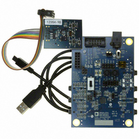
Description
Eval Board For ADAU1761
Manufacturer
Analog Devices Inc
Series
SigmaDSP®r
Specifications of EVAL-ADAU1761Z
Main Purpose
Audio, CODEC
Embedded
Yes, DSP
Utilized Ic / Part
ADAU1761
Primary Attributes
Stereo, 24-Bit, 8 ~ 96 kHz Sampling Rate, GUI Tool
Secondary Attributes
I²C and GPIO Interfaces, 2 Differential and 1 Stereo Single-Ended Analog Inputs and Outputs
Silicon Manufacturer
Analog Devices
Core Architecture
SigmaDSP
Silicon Core Number
ADAU1761
Silicon Family Name
SigmaDSP
Application Sub Type
Audio
Lead Free Status / RoHS Status
Lead free / RoHS Compliant
Available stocks
Company
Part Number
Manufacturer
Quantity
Price
Company:

Part Number:
EVAL-ADAU1761Z
Manufacturer:
Analog Devices Inc
Quantity:
135


USING THE EVALUATION BOARD
ADAU1761 SigmaDSP
The ADAU1761 is a low power, stereo audio codec with
integrated digital audio processing that supports stereo 48 kHz
record and playback at 10 mW from a 1.8 V analog supply. The
stereo audio ADCs and DACs support sample rates from 8 kHz
to 96 kHz as well as a digital volume control.
The SigmaDSP core features 28-bit processing (56-bit double
precision). The processor allows system designers to compensate
for the real-world limitations of microphones, speakers, amplifiers,
and listening environments, resulting in a dramatic improvement
in the perceived audio quality through equalization, multiband
compression, limiting, and third-party branded algorithms.
The SigmaStudio graphical development tool is used to program
the ADAU1761. This software includes audio processing blocks
such as filters, dynamics processors, mixers, and low level DSP
functions for fast development of custom signal flows.
The record path includes an integrated microphone bias circuit
and six inputs. The inputs can be mixed and muxed before the
ADC, or they can be configured to bypass the ADC. The
ADAU1761 includes a stereo digital microphone input.
The ADAU1761 includes five high power output drivers (two
differential and three single-ended) that support stereo head-
phones, an earpiece, or other output transducers. AC-coupled
or capless configurations are supported. Individual fine level
controls are supported on all analog outputs. The output mixer
stage allows for flexible routing of audio.
POWER
The evaluation board uses the
regulator to generate either 3.3 V or 1.8 V for the board. The
output voltage VDD of the ADP3336 is set with external resistors,
which can be switched with S1 to select either 3.3 V or 1.8 V
outputs (see Table 1).
Table 1. VDD Voltage Settings
Voltage Regulator
Output (V)
3.3
1.8
The maximum operating current draw from this board is
approximately 75 mA. This maximum value is reached with
VDD = 3.3 V, a large SigmaDSP program loaded, headphone
outputs enabled, and all LEDs enabled.
Typically, the regulator input comes from the USBi +5 V dc USB
supply on Header J1. This supply is enabled with a jumper on
J5. To use another +5 V dc supply source, remove the jumper
on J5, and connect the other supply either on the J2 power jack
(positive tip) or via soldering leads from a supply such as a
battery to J3. On J3, Pin 1 (square pad) is ground, and Pin 2
(circle pad) is the power connection.
S1 Setting
Up
Down
ADP3336
low dropout voltage
Rev. 0 | Page 5 of 12
When the ADP3336 is outputting a regulated voltage, LED D1
is illuminated red.
VDD is connected to the AVDD pin of the ADAU1761 with
Jumper J17. To connect the ADAU1761 IOVDD pin to the same
supply, connect J16, also. These headers can also be used to
separate the supplies of the ADAU1761 from the rest of the
board and to connect an external supply to the ADAU1761.
L1 and C24 are connected to the AVDD pin of the ADAU1761
and function as an L-C filter to reject high frequency power
supply noise common in GSM mobile applications. This filter is
tuned to approximately 1.5 GHz.
ANALOG AUDIO INPUT
The EVAL-ADAU1761Z has three ac-coupled 1/8” input jacks:
two mono differential jacks and one stereo single-ended jack.
The tips of the differential input jacks, J20 and J22 (labeled IN 1
and IN 2), are connected to the negative input of the ADAU1761,
and the rings are connected to the positive input. The stereo
single-ended input on J24 (labeled IN 3) is connected to the
LAUX and RAUX inputs of the ADAU1761. IN 1 and IN 2
can also be configured to bias a microphone. This is enabled
by connecting the MICBIAS pin of the ADAU1761 to the tip
of the input connectors with Jumper J15 and Jumper J18.
At VDD = 3.3 V, the full-scale analog input level of the
EVAL-ADAU1761Z is 1.0 V rms (1.0 V rms on the single-ended
inputs and 0.5 V rms on each of the two pins of the differential
inputs). The full-scale input level scales with VDD.
ANALOG AUDIO OUTPUT
The EVAL-ADAU1761Z has four 1/8” output jacks: two
mono differential, one stereo single-ended, and one stereo
capless headphone output. The differential outputs on J21
and J25 (labeled DIFF OUT L and DIFF OUT R, respectively)
are biased at AVDD/2 V. The tips of the differential output jacks
are connected to the positive output of the ADAU1761, and the
rings are connected to the negative outputs. J23 is a stereo,
single-ended, ac-coupled output.
At VDD = 3.3 V, the full-scale analog output level of the
EVAL-ADAU1761Z is 1.0 V rms (1.0 V rms on the single-ended
outputs and 0.5 V rms on each of the two pins of the differential
outputs). The differential line outputs of the ADAU1761 can
each be boosted by 6 dB to 2.0 V rms. The full-scale output level
scales with VDD.
Note that Jack J21 and Jack J25 tie the ring to the sleeve, resulting
in a floating ground output. Be aware of this when connecting
to these outputs.
EVAL-ADAU1761Z
Related parts for EVAL-ADAU1761Z
Image
Part Number
Description
Manufacturer
Datasheet
Request
R


Part Number:
Description:
BOARD EVAL FOR SI270X-A
Manufacturer:
Silicon Laboratories Inc
Datasheet:

Part Number:
Description:
BUCK CONV REF DESIGN KIT IP1201
Manufacturer:
International Rectifier
Datasheet:
Part Number:
Description:
BOARD DEMO SYNC DUAL BUCK CNVTER
Manufacturer:
International Rectifier
Datasheet:
Part Number:
Description:
BOARD DEMO SYNC BUCK CONVETER
Manufacturer:
International Rectifier
Datasheet:

Part Number:
Description:
EVALBOARD/EB Omnidirectional microphone - Analog
Manufacturer:
Analog Devices
Datasheet:
Part Number:
Description:
EVALBOARD/EB Omnidirectional microphone - Analog
Manufacturer:
Analog Devices
Datasheet:


Part Number:
Description:
BOARD EVAL LED DRIVER LT3756
Manufacturer:
Linear Technology
Datasheet:

Part Number:
Description:
BOARD EVAL FOR AD7741/7742
Manufacturer:
Analog Devices Inc
Datasheet:

Part Number:
Description:
±1.7g Dual-Axis IMEMS Accelerometer Evaluation Board
Manufacturer:
Analog Devices Inc
Datasheet:

Part Number:
Description:
IC MULTIPLIER ANALOG 8-SOIC T/R
Manufacturer:
Analog Devices Inc
Datasheet:

Part Number:
Description:
IC ANALOG MULTIPLIER 8-DIP
Manufacturer:
Analog Devices Inc
Datasheet:
Part Number:
Description:
IC ANALOG MULTIPLIER 8-SOIC
Manufacturer:
Analog Devices Inc
Datasheet:
Part Number:
Description:
IC ANALOG MULTIPLIER 8-DIP
Manufacturer:
Analog Devices Inc
Datasheet: