AD7821KPZ Analog Devices Inc, AD7821KPZ Datasheet - Page 10
AD7821KPZ
Manufacturer Part Number
AD7821KPZ
Description
8-BIT ATC CONVERTER IC
Manufacturer
Analog Devices Inc
Datasheet
1.AD7821KRZ-REEL.pdf
(16 pages)
Specifications of AD7821KPZ
Number Of Bits
8
Sampling Rate (per Second)
1M
Data Interface
Parallel
Number Of Converters
3
Power Dissipation (max)
50mW
Voltage Supply Source
Dual ±
Operating Temperature
-40°C ~ 85°C
Mounting Type
Surface Mount
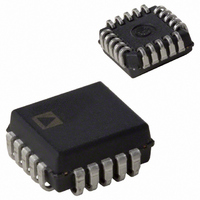
Package / Case
20-LCC (J-Lead)
Lead Free Status / RoHS Status
Lead free / RoHS Compliant
Available stocks
Company
Part Number
Manufacturer
Quantity
Price

Company:
Part Number:
AD7821KPZ
Manufacturer:
Analog Devices Inc
Quantity:
10 000
Company:
Part Number:
AD7821KPZ-REEL
Manufacturer:
Analog Devices Inc
Quantity:
10 000


AD7821
RD Mode (MODE = 0)
The timing diagram for the RD mode is shown in Figure 11.
This mode is intended for use with microprocessors that have a
WAIT state facility, whereby a READ instruction cycle can be
extended to accommodate slow memory devices. A conversion
is started by taking CS and RD low (READ operation). Both
CS and RD are then kept low until output data appears.
In this mode, Pin 6 of the AD7821 is configured as a status out-
put, RDY. This RDY output can be used to drive the processor
READY or WAIT input. It is an open-drain output (no inter-
nal-pull-up device) which goes low after the falling edge of CS
and goes high impedance at the end of conversion. An INT line is
also provided which goes low when a conversion is complete.
INT returns high on the rising edge of CS or RD.
WR-RD Mode (MODE = 1)
In the WR-RD mode, Pin 6 is configured as a WRITE (WR)
input for the AD7821. With CS low, conversion is initiated on
the falling edge of WR. Two options exist for reading data from
the converter.
In the first of these options the processor waits for the INT status
line to go low before reading the data (see Figure 12a).
INT typically goes low within 380 ns after the rising edge of WR.
It indicates that conversion is complete and that the data result is
in the output latch. With CS low, the data outputs (DB0–DB7)
are activated when RD goes low. INT is reset by the rising edge
of RD or CS.
Figure 11. RD Mode
–10–
The alternative option can be used to shorten the conversion time.
This is a method for bypassing the internal time-out circuit. The
INT line is ignored and RD can be brought low 250 ns after the
rising edge of WR. In this case RD going low transfers the data
result into the output latch and activates the data output
(DB0–DB7). INT is driven low on the falling edge of RD and is
reset on the rising edge of RD or CS. The timing for this interface
is shown in Figure 12b.
The AD7821 can also be used in standalone operation in the
WR-RD mode. CS and RD are tied low, and a conversion is initi-
ated by bringing WR low. Output data is valid 530 ns (t
after the rising edge of WR. The timing diagram for this mode is
shown in Figure 13.
Figure 13. WR-RD Mode Stand-Alone Operation,
CS = RD = 0
Figure 12b. WR-RD Mode (t
Figure 12a. WR-RD Mode (t
RD
RD
> t
< t
INTL
INTL
)
)
INTL
REV. B
+ t
ID
)
Related parts for AD7821KPZ
Image
Part Number
Description
Manufacturer
Datasheet
Request
R

Part Number:
Description:
±1.7g Dual-Axis IMEMS Accelerometer Evaluation Board
Manufacturer:
Analog Devices Inc
Datasheet:

Part Number:
Description:
Inertial Sensor Evaluation System
Manufacturer:
Analog Devices Inc
Datasheet:
Part Number:
Description:
Manufacturer:
Analog Devices Inc
Datasheet:
Part Number:
Description:
Manufacturer:
Analog Devices Inc
Datasheet:
Part Number:
Description:
Manufacturer:
Analog Devices Inc
Datasheet:
Part Number:
Description:
Manufacturer:
Analog Devices Inc
Datasheet:
Part Number:
Description:
Manufacturer:
Analog Devices Inc
Datasheet:
Part Number:
Description:
Manufacturer:
Analog Devices Inc
Datasheet:
Part Number:
Description:
Manufacturer:
Analog Devices Inc
Datasheet:
Part Number:
Description:
Manufacturer:
Analog Devices Inc
Datasheet:
Part Number:
Description:
Manufacturer:
Analog Devices Inc
Datasheet:
Part Number:
Description:
Manufacturer:
Analog Devices Inc
Datasheet:
Part Number:
Description:
Manufacturer:
Analog Devices Inc
Datasheet: