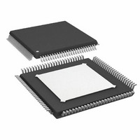
AD9272BSVZ-40 Analog Devices Inc, AD9272BSVZ-40 Datasheet - Page 25

AD9272BSVZ-40
Manufacturer Part Number
AD9272BSVZ-40
Description
12Bit 40 MSPS Octal ADC
Manufacturer
Analog Devices Inc
Type
Ultrasound Receiversr
Datasheet
1.AD9272BSVZ-80.pdf
(44 pages)
Specifications of AD9272BSVZ-40
Design Resources
Powering AD9272 with ADP5020 Switching Regulator PMU for Increased Efficiency (CN0135)
Resolution (bits)
12 b
Sampling Rate (per Second)
40M
Data Interface
Serial
Voltage Supply Source
Analog and Digital
Voltage - Supply
1.8V, 3V
Operating Temperature
-40°C ~ 85°C
Mounting Type
Surface Mount
Package / Case
100-TQFP Exposed Pad, 100-eTQFP, 100-HTQFP, 100-VQFP
Lead Free Status / RoHS Status
Lead free / RoHS Compliant
For Use With
AD9272-65EBZ - BOARD EVAL AD9272
Lead Free Status / RoHS Status
Lead free / RoHS Compliant
Available stocks
Company
Part Number
Manufacturer
Quantity
Price
Company:
Part Number:
AD9272BSVZ-40
Manufacturer:
Analog Devices Inc
Quantity:
135
Company:
Part Number:
AD9272BSVZ-40
Manufacturer:
ADI
Quantity:
526
Company:
Part Number:
AD9272BSVZ-40
Manufacturer:
Analog Devices Inc
Quantity:
10 000
Part Number:
AD9272BSVZ-40
Manufacturer:
ADI/亚德诺
Quantity:
20 000
INPUT OVERDRIVE
Excellent overload behavior is of primary importance in
ultrasound. Both the LNA and VGA have built-in overdrive
protection and quickly recover after an overload event.
Input Overload Protection
As with any amplifier, voltage clamping prior to the inputs is
highly recommended if the application is subject to high
transient voltages.
In Figure 43, a simplified ultrasound transducer interface is
shown. A common transducer element serves the dual functions
of transmitting and receiving ultrasound energy. During the
transmitting phase, high voltage pulses are applied to the ceramic
elements. A typical transmit/receive (T/R) switch can consist of
four high voltage diodes in a bridge configuration. Although the
diodes ideally block transmit pulses from the sensitive receiver
input, diode characteristics are not ideal, and the resulting leakage
transients imposed on the LI-x inputs can be problematic.
Because ultrasound is a pulse system and time-of-flight is used to
determine depth, quick recovery from input overloads is essential.
Overload can occur in the preamp and the VGA. Immediately
following a transmit pulse, the typical VGA gains are low, and
the LNA is subject to overload from T/R switch leakage. With
increasing gain, the VGA can become overloaded due to strong
echoes that occur near field echoes and acoustically dense materials,
such as bone.
Figure 43 illustrates an external overload protection scheme. A
pair of back-to-back signal diodes is installed prior to installing the
ac-coupling capacitors. Keep in mind that all diodes shown in
this example are prone to exhibiting some amount of shot noise.
Many types of diodes are available for achieving the desired
noise performance. The configuration shown in Figure 43 tends
to add 2 nV/√Hz of input-referred noise. Decreasing the 5 kΩ
resistor and increasing the 2 kΩ resistor may improve noise
contribution, depending on the application. With the diodes
shown in Figure 43, clamping levels of ±0.5 V or less
significantly enhance the overload performance of the system.
DRIVER
Tx
TRANSDUCER
Figure 43. Input Overload Protection
5kΩ
5kΩ
+5V
–5V
HV
2kΩ
10nF
10nF
AD9272
LNA
Rev. C | Page 25 of 44
CW DOPPLER OPERATION
Modern ultrasound machines used for medical applications
employ a 2
typical array sizes of 16 or 32 receiver channels phase-shifted
and summed together to extract coherent information. When
used in multiples, the desired signals from each channel can be
summed to yield a larger signal (increased by a factor N, where
N is the number of channels), and the noise is increased by the
square root of the number of channels. This technique enhances
the signal-to-noise performance of the machine. The critical
elements in a beam-former design are the means to align the
incoming signals in the time domain and the means to sum the
individual signals into a composite whole.
Beam forming, as applied to medical ultrasound, is defined as the
phase alignment and summation of signals that are generated
from a common source but received at different times by a
multi-element ultrasound transducer. Beam forming has two
functions: it imparts directivity to the transducer, enhancing its
gain, and it defines a focal point within the body from which the
location of the returning echo is derived.
The AD9272 includes the front-end components needed to
implement analog beam forming for CW Doppler operation.
These components allow CW channels with similar phases to be
coherently combined before phase alignment and down mixing,
thus reducing the number of delay lines or adjustable phase shifters/
down mixers
are used, the phase alignment is performed, and then the channels
are coherently summed and down converted by a dynamic range
I/Q demodulator. Alternatively, if phase shifters/down mixers,
such as the AD8333 and AD8339, are used, phase alignment
and down conversion are done before coherently summing all
channels into I/Q signals. In either case, the resultant I and Q
signals are filtered and sampled by two high resolution ADCs,
and the sampled signals are processed to extract the relevant
Doppler information.
Alternately, the LNA of the AD9272 can directly drive the AD8333
or AD8339 without the crosspoint switch. The LO-x pin presents
the inverting LNA output, and the LOSW-x pin can be configured
via Register 0x2C (see Table 17) to connect to the noninverting
output to provide a differential output of the LNA. The LNA output
full-scale voltage of the AD9272 is 4.4 V p-p, and the input full-
scale voltage is 2.7 V p-p. If no attenuation is provided between
the LNA output and the demodulator, the LNA input full-scale
voltage must be limited.
N
binary array of receivers for beam forming, with
(AD8333
or AD8339) required. Next, if delay lines
AD9272


