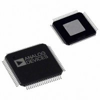
AD9410BSVZ Analog Devices Inc, AD9410BSVZ Datasheet - Page 2

AD9410BSVZ
Manufacturer Part Number
AD9410BSVZ
Description
10 BIT 210 MSPS ADC
Manufacturer
Analog Devices Inc
Datasheet
1.AD9410BSVZ.pdf
(20 pages)
Specifications of AD9410BSVZ
Number Of Bits
10
Sampling Rate (per Second)
210M
Data Interface
Parallel
Number Of Converters
1
Power Dissipation (max)
2.4W
Voltage Supply Source
Analog and Digital
Operating Temperature
-40°C ~ 85°C
Mounting Type
Surface Mount
Package / Case
80-TQFP Exposed Pad, 80-eTQFP, 80-HTQFP, 80-VQFP
Lead Free Status / RoHS Status
Lead free / RoHS Compliant
Available stocks
Company
Part Number
Manufacturer
Quantity
Price
Company:
Part Number:
AD9410BSVZ
Manufacturer:
ADI
Quantity:
115
Company:
Part Number:
AD9410BSVZ
Manufacturer:
Analog Devices Inc
Quantity:
10 000
AD9410
TABLE OF CONTENTS
Features .............................................................................................. 1
Applications....................................................................................... 1
Functional Block Diagram .............................................................. 1
General Description ......................................................................... 1
Product Highlights ........................................................................... 1
Revision History ............................................................................... 2
Specifications..................................................................................... 3
Absolute Maximum Ratings............................................................ 7
REVISION HISTORY
7/07—Rev. 0 to Rev. A
Updated Format..................................................................Universal
Deleted 80-Lead LQFP_EP ...............................................Universal
Added 80-Lead TQFP_EP.................................................Universal
Changes to Figure 1 and General Description ............................. 1
Changes to Table 2 and Table 3....................................................... 4
Changes to Figure 2.......................................................................... 6
Changes to Note 1............................................................................. 7
Changes to Figure 3 and Table 6..................................................... 8
Changes to Terminology Section.................................................. 10
Changes to Figure 6........................................................................ 12
Deleted Evaluation Board Section................................................ 14
Renamed Encode Input Section, Clock Input Section and
Changes to Clock Input Section, Clock Outputs (DCO, DCO )
Section, Figure 26, and Figure 27 ................................................. 16
Changes to Data Sync (DS) Section ............................................. 17
Changes to Figure 29...................................................................... 18
Updated Outline Dimensions ....................................................... 19
Changes to Ordering Guide .......................................................... 19
DC Specifications ......................................................................... 3
Switching Specifications .............................................................. 4
Digital Specifications ................................................................... 4
AC Specifications.......................................................................... 5
Explaination of Test Levels.......................................................... 7
ESD Caution.................................................................................. 7
Rev. A | Page 2 of 20
Pin Configuration and Function Descriptions..............................8
Terminology .................................................................................... 10
Typical Performance Characteristics ........................................... 13
Theory of Operation ...................................................................... 16
Outline Dimensions ....................................................................... 19
10/00—Revision 0: Initial Version
Equivalent Circuits..................................................................... 12
Using the AD9410 ...................................................................... 16
Analog Input ............................................................................... 16
Digital Outputs ........................................................................... 16
Clock Outputs (DCO, DCO ).................................................... 16
Voltage Reference ....................................................................... 17
Timing ......................................................................................... 17
Data Sync (DS) ........................................................................... 17
Ordering Guide .......................................................................... 19


