MT9T031C12STC Aptina LLC, MT9T031C12STC Datasheet - Page 27
MT9T031C12STC
Manufacturer Part Number
MT9T031C12STC
Description
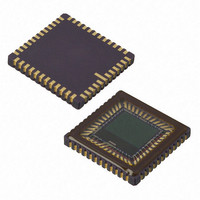
IC SENSOR IMAGE COLOR 48CLCC
Manufacturer
Aptina LLC
Series
Micron®DigitalClarity®r
Type
CMOS Imagingr
Datasheets
1.MT9T031C12STCH_ES.pdf
(12 pages)
2.MT9T031C12STCH_ES.pdf
(2 pages)
3.MT9T031C12STC.pdf
(2 pages)
4.MT9T031C12STC.pdf
(46 pages)
Specifications of MT9T031C12STC
Pixel Size
3.2µm x 3.2µm
Active Pixel Array
2048H x 1536V
Frames Per Second
12 ~ 93
Voltage - Supply
3 V ~ 3.6 V
Package / Case
48-CLCC
Brief Features
Superior Low Light Performance, Programmable Controls, Low Dark Current, High Frame Rate
Supply Voltage Range
3V To 3.6V
Operating Temperature Range
0°C To +60°C
Ic Function
Digital Image Sensor
Lead Free Status / RoHS Status
Lead free / RoHS Compliant
For Use With
557-1450 - KIT HEAD BOARD FOR MT9T031557-1451 - KIT DEV FOR MT9T031
Lead Free Status / Rohs Status
Compliant
Other names
557-1452
Available stocks
Company
Part Number
Manufacturer
Quantity
Price

Part Number:
MT9T031C12STC
Manufacturer:
APTINA
Quantity:
20 000


Strobe Pulse Output
Table 10:
Global Shutter Release Snapshot Mode
Programmed Exposure Mode
PDF: 3682685119/Source: 9830567334
MT9T031_DS - Rev.E 5/11 EN
STROBE Pulse Output
Note:
1. Set up snapshot mode as normal (including any STROBE preferences).
2. Set R0x21 (Read Mode 3) to 0x0003.
3. Assert (transition LOW to HIGH) the GSHT_CTL pin to reset the array. This pin must
4. Negate (transition HIGH to LOW) the GSHT_CTL pin to begin the exposure. The
5. Row readout begins automatically. The mechanical shutter should be closed before
The STROBE pulse must be enabled before use by setting R0x1E [bit 9] = 1. The STROBE
signal has two options for pulse length and may be selected using R0x1E [bit 10] as
shown in Table 10.
After the TRIGGER pulse has signaled a snapshot operation, each row of the imager
array is reset in sequence to clear out any accumulated signal. Once each row of the
imager is reset, the STROBE pulse is output from the imager with a length dependent
upon the characteristics described above. After the STROBE pulse goes low, the imager
waits 16 additional rows and then each row from the pixel array is read out. No STROBE
is generated unless the shutter width is greater than the output image height plus
vertical blanking.
R0x1E and R0x21
In addition to the standard snapshot mode, the MT9T031 has a global shutter release
mode which may be combined with a mechanical shutter to achieve simultaneous
exposure of all rows in the image.
Two global shutter modes are available: programmed exposure and bulb mode. In
programmed exposure mode, the exposure time is dictated by {R0x08, R0x09} (Shutter
Width). In bulb mode, the TRIGGER and GSHT_CTL pins are used to achieve an arbi-
trary exposure time.
To use programmed exposure mode:
remain HIGH for 18820 PIXCLKs.
exposure starts 1000 PIXCLKs after the falling edge of GSHT_CTL.
Unlike normal snapshot mode, R0x0B (Restart) may not be used to initiate the expo-
sure in global shutter modes.
row read out begins. The trailing edge of STROBE (if enabled) occurs ((65536 x R0x08 +
R0x09) x
active window starts the lesser of 16 x
R0
x
t
1E, Bit 10
ROW
0
1
+ 2000) PIXCLKs after the falling edge of GSHT_CTL. Readout of the
27
1 row time (default)
((65536 x R0x08 + R0x09 – R) -16) x
MT9T031: 1/2-Inch 3-Mp Digital Image Sensor
t
ROW
or (R0x06 + 1) x
STROBE Pulse Width
t
ROW
t
ROW
©2006 Aptina Imaging Corporation. All rights reserved.
- V
later.
Feature Description
Related parts for MT9T031C12STC
Image
Part Number
Description
Manufacturer
Datasheet
Request
R

Part Number:
Description:
SENSOR IMAGE VGA COLOR CMOS PLCC
Manufacturer:
Aptina LLC
Datasheet:

Part Number:
Description:
SENSOR IMAGE 1.3MP CMOS 48-CLCC
Manufacturer:
Aptina LLC
Datasheet:

Part Number:
Description:
SENSOR IMAGE 2MP CMOS 48-CLCC
Manufacturer:
Aptina LLC
Datasheet:

Part Number:
Description:
SENSOR IMAGE VGA MONO 52IBGA
Manufacturer:
Aptina LLC
Datasheet:

Part Number:
Description:
SENSOR IMAGE VGA COLOR 48CLCC
Manufacturer:
Aptina LLC
Datasheet:

Part Number:
Description:
SENSOR IMAGE COLOR CMOS 48-PLCC
Manufacturer:
Aptina LLC
Datasheet:

Part Number:
Description:
KIT HEAD BOARD FOR MT9P031
Manufacturer:
Aptina LLC
Datasheet:

Part Number:
Description:
KIT HEAD BOARD FOR MT9D131
Manufacturer:
Aptina LLC
Datasheet:

Part Number:
Description:
KIT HEAD BOARD FOR MT9P031
Manufacturer:
Aptina LLC
Datasheet:

Part Number:
Description:
KIT HEAD BOARD FOR MT9M032
Manufacturer:
Aptina LLC
Datasheet:

Part Number:
Description:
PARALLEL HEADBOARD FOR MT9M032
Manufacturer:
Aptina LLC
Datasheet:
Part Number:
Description:
SENSOR IMAGE VGA COLOR CMOS PLCC
Manufacturer:
Aptina LLC
Datasheet:
Part Number:
Description:
SENSOR IMAGE 2MP CMOS 48-CLCC
Manufacturer:
Aptina LLC
Datasheet:
